276
Chapter 5
Troubleshooting the IF Section
Troubleshooting the A15 Motherboard Assembly
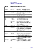
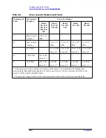
Table 5-7
A15 Motherboard Pin Designations
Mnemonic
Instrument Assemblies
Card
Cages
a
A7
A8
A9
A11
A12
A13
A14
A16
Slots 1,
2, 3, 4
A15J1
A15J13
A15J7
A15J8
A15J9
A15J10
A15J11
A15J12
A15J2
A15J3,
4, 5, 6
21.4 MHz IF
9
22, 23
1
20
22,
23
b
44
+10 V
22
c
29
29
+12 V
13, 32
27, 57
+15 V
3, 33
1, 2,
3, 20,
21,
22
27
8, 18
27
8, 38
9, 39
+5 V
19, 49
9, 10,
11,
12,
28,
29,
30,
31
10, 20
25,
26,
55, 56
26, 56
−
15 V
4, 34
4, 5,
6, 23,
24,
25
6, 16
25
9, 39
10, 40
−
8 VT
23
8
ACOM
2, 32
7, 26,
27
1-8,
10,
12,
14,
16,
18,
20
1-21,
24-26,
28,
33- 44
2-5,
7, 9,
11-15,
17, 19
5- 10,
15- 19
1- 21,
24-26,
28,
33- 44
1, 3-7,
9-24,
26,
28-30,
32-37,
41-43
2, 4,
6,
32- 37
2, 4, 6,
8, 29,
31-38,
59, 60
ADC_SYNC
30
27
ADR0
6
11
12
ADR1
36
41
42
ADR2
7
12
13
Summary of Contents for 8590L
Page 29: ...30 Chapter1 Introduction If You Replace or Repair an Assembly ...
Page 175: ...176 Chapter2 Making Adjustments 28 Correcting for Absolute Amplitude Accuracy for Option 051 ...
Page 279: ...280 Chapter5 Troubleshooting the IF Section Troubleshooting the A15 Motherboard Assembly ...
Page 347: ...348 Chapter7 Replacing Major Assemblies Rear Frame Assembly ...
Page 355: ...356 Chapter8 If You Have A Problem Returning Your Analyzer for Service ...
Page 379: ...380 Chapter9 Assembly Descriptions and Block Diagrams IF Section ...
Page 380: ......
Page 381: ...382 Chapter9 Assembly Descriptions and Block Diagrams IF Section ...
Page 382: ......
Page 383: ...384 Chapter9 Assembly Descriptions and Block Diagrams IF Section ...
Page 384: ......
Page 385: ...386 Chapter9 Assembly Descriptions and Block Diagrams IF Section ...
Page 386: ......
Page 387: ...388 Chapter9 Assembly Descriptions and Block Diagrams IF Section ...
Page 388: ......
Page 389: ...390 Chapter9 Assembly Descriptions and Block Diagrams IF Section ...
Page 390: ......
Page 391: ...392 Chapter9 Assembly Descriptions and Block Diagrams IF Section ...
Page 392: ...393 10 Analyzer Options and Block Diagrams ...
Page 443: ...444 Chapter10 Analyzer Options and Block Diagrams Option 190 DVB C Service Menus ...
Page 444: ......
Page 445: ...446 Chapter10 Analyzer Options and Block Diagrams Option 190 DVB C Service Menus ...
Page 446: ......
Page 447: ...448 Chapter10 Analyzer Options and Block Diagrams Option 190 DVB C Service Menus ...
Page 448: ......
Page 449: ...450 Chapter10 Analyzer Options and Block Diagrams Option 190 DVB C Service Menus ...
Page 451: ...452 Chapter10 Analyzer Options and Block Diagrams Option 190 DVB C Service Menus ...
Page 483: ...484 Chapter11 Major Assembly and Cable Locations Major Assembly and Cable Locations ...
Page 537: ...538 Chapter12 Replaceable Parts Component Level Information Packets ...
Page 538: ......
Page 539: ...540 Chapter12 Replaceable Parts Component Level Information Packets ...
Page 540: ......
Page 541: ...542 Chapter12 Replaceable Parts Component Level Information Packets ...
Page 542: ...FOLDOUT 12 3 8590L AND 8591E RF ASSEMBLY ...
Page 543: ...544 Chapter12 Replaceable Parts Component Level Information Packets ...
Page 544: ......
Page 545: ...546 Chapter12 Replaceable Parts Component Level Information Packets ...
Page 546: ......
Page 547: ...548 Chapter12 Replaceable Parts Component Level Information Packets ...
Page 548: ......
Page 549: ...550 Chapter12 Replaceable Parts Component Level Information Packets ...
Page 550: ......
Page 551: ...552 Chapter12 Replaceable Parts Component Level Information Packets ...
Page 665: ...666 Chapter15 Service Equipment and Tools Service Equipment and Tools ...
Page 666: ...667 16 Safety and Regulatory Information ...
Page 673: ...674 Chapter16 Safety and Regulatory Information Protection from Electrostatic Discharge ...

