426
Chapter 10
Analyzer Options and Block Diagrams
First LO Distribution Amplifier (LODA) 8593E, 8594E, 8594Q, 8595E, 8596E Option 009
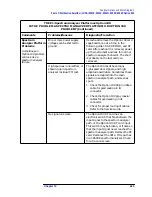
TREE 3: Option 190
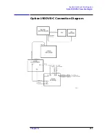
HOW DO I CHECK THE BASIC CONFIGURATION?
Comments
Problems/Reasons
Diagnostic/Fix Action
The Option 190 consists of three
card-cage option cards, DSP
firmware, host analyzer firmware,
and the DLP. All revisions must
be up to date.
Access the option listing under
Show Options
. Confirm that the
option software revisions are
current, and that no configuration
error message shows. The following
is a list of the initial revisions.
• Firmware: 961216
• DLP: 961218
• Option 190 DSP: 961206
If you get a configuration error,
refer to the “Error Messages”
section of the 8594Q Option 190
DVB-C QAM Analyzer User's Guide.
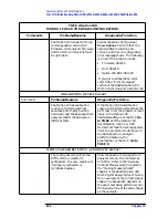
WHICH OPTION 190 TEST FAILED?
Comments
Problems/Reasons
Diagnostic/Fix Action
The Option 190 Recalibration
routine or DVB Demod Test
exercises both the Option 190
hardware, and the base spectrum
analyzer platform hardware in
different tests.
If the Option 190 Recalibration
routine or DVB Demod Test fails the
EVM test limit, the problem is most
likely in the Option 190
hardware/software or the DLP. Go
to TREE 4. If the Option 190
Recalibration routine or DVB
Demod Test fails the average power
limit, the problem is most likely in
the basic spectrum analyzer
platform hardware, the
preamplifier, or the DLP. Go to
TREE 5.
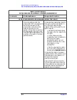
IS THE ANALYZER RECEIVING A GOOD INPUT SIGNAL?
The test signal comes from the
8770 arbitrary waveform
synthesizer. It is very sensitive to
improperly connected or
terminated cables.
View the spectrum on a spectrum
analyzer screen. It is centered at
27.6 MHz. Refer to the “Average
Channel Measurement” located in
the “Making Measurements”
chapter of the 8594Q Option 190
DVB-C QAM Analyzer User's Guide,
for an example of the correct signal
shape. The bandwidth depends on
the exact test being performed, but
the signal will be of the same shape
as the example.
Summary of Contents for 8590L
Page 29: ...30 Chapter1 Introduction If You Replace or Repair an Assembly ...
Page 175: ...176 Chapter2 Making Adjustments 28 Correcting for Absolute Amplitude Accuracy for Option 051 ...
Page 279: ...280 Chapter5 Troubleshooting the IF Section Troubleshooting the A15 Motherboard Assembly ...
Page 347: ...348 Chapter7 Replacing Major Assemblies Rear Frame Assembly ...
Page 355: ...356 Chapter8 If You Have A Problem Returning Your Analyzer for Service ...
Page 379: ...380 Chapter9 Assembly Descriptions and Block Diagrams IF Section ...
Page 380: ......
Page 381: ...382 Chapter9 Assembly Descriptions and Block Diagrams IF Section ...
Page 382: ......
Page 383: ...384 Chapter9 Assembly Descriptions and Block Diagrams IF Section ...
Page 384: ......
Page 385: ...386 Chapter9 Assembly Descriptions and Block Diagrams IF Section ...
Page 386: ......
Page 387: ...388 Chapter9 Assembly Descriptions and Block Diagrams IF Section ...
Page 388: ......
Page 389: ...390 Chapter9 Assembly Descriptions and Block Diagrams IF Section ...
Page 390: ......
Page 391: ...392 Chapter9 Assembly Descriptions and Block Diagrams IF Section ...
Page 392: ...393 10 Analyzer Options and Block Diagrams ...
Page 443: ...444 Chapter10 Analyzer Options and Block Diagrams Option 190 DVB C Service Menus ...
Page 444: ......
Page 445: ...446 Chapter10 Analyzer Options and Block Diagrams Option 190 DVB C Service Menus ...
Page 446: ......
Page 447: ...448 Chapter10 Analyzer Options and Block Diagrams Option 190 DVB C Service Menus ...
Page 448: ......
Page 449: ...450 Chapter10 Analyzer Options and Block Diagrams Option 190 DVB C Service Menus ...
Page 451: ...452 Chapter10 Analyzer Options and Block Diagrams Option 190 DVB C Service Menus ...
Page 483: ...484 Chapter11 Major Assembly and Cable Locations Major Assembly and Cable Locations ...
Page 537: ...538 Chapter12 Replaceable Parts Component Level Information Packets ...
Page 538: ......
Page 539: ...540 Chapter12 Replaceable Parts Component Level Information Packets ...
Page 540: ......
Page 541: ...542 Chapter12 Replaceable Parts Component Level Information Packets ...
Page 542: ...FOLDOUT 12 3 8590L AND 8591E RF ASSEMBLY ...
Page 543: ...544 Chapter12 Replaceable Parts Component Level Information Packets ...
Page 544: ......
Page 545: ...546 Chapter12 Replaceable Parts Component Level Information Packets ...
Page 546: ......
Page 547: ...548 Chapter12 Replaceable Parts Component Level Information Packets ...
Page 548: ......
Page 549: ...550 Chapter12 Replaceable Parts Component Level Information Packets ...
Page 550: ......
Page 551: ...552 Chapter12 Replaceable Parts Component Level Information Packets ...
Page 665: ...666 Chapter15 Service Equipment and Tools Service Equipment and Tools ...
Page 666: ...667 16 Safety and Regulatory Information ...
Page 673: ...674 Chapter16 Safety and Regulatory Information Protection from Electrostatic Discharge ...


