430
Chapter 10
Analyzer Options and Block Diagrams
First LO Distribution Amplifier (LODA) 8593E, 8594E, 8594Q, 8595E, 8596E Option 009
Failures can appear
in multiple places in
the EVM test across
multiple-channel
bandwidths and
symbol rates,
regardless of the
preamplifier settings.
The problem is in the main
demodulation path used by all EVM
test modes.
1. Check the adjustment of the
71.025 MHz oscillator on the RF
option board. The nominal setting at
room temperature after warmup and
instrument preset (
PRESET
) of the
instrument should be 71.025 MHz.
If it has drifted off frequency, use
a tweaker to adjust C402 to bring
the frequency to 71.025 MHz.
Watch the signal. Is it stable, or
does it drift again?
If it drifts again, Q400 is
probably bad. Q400 is a specially
selected 2N3904 transistor. Check
with the division to obtain an
approved replacement.
Rerun the EVM test to check if the
problem is resolved. If not, proceed to
.
2. Replace the RF board with a
“known” good board. Does the
instrument now pass the EVM
test?
If so, save the bad board and the
matching test data for division
analysis.
If not, continue to
.
3. Replace the DEMOD option board
with a “known” good board. Does the
instrument now pass the EVM test?
If so, save the bad board and the
matching test data for division
analysis.
If not, continue to
.
4. Replace the DSP option board with
a “known” good board. Does the
instrument now pass the EVM test?
If so, save the bad board and the
matching test data for division
analysis.
If not, after swapping to a full set
of “known” good boards, set the
instrument aside for further
analysis.
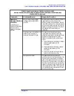
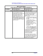
TREE 4: EVM Problems
IS THE FAILURE IN A SINGLE CHANNEL BANDWIDTH?
Comments
Problems/Reasons
Diagnostic/Fix Action
Summary of Contents for 8590L
Page 29: ...30 Chapter1 Introduction If You Replace or Repair an Assembly ...
Page 175: ...176 Chapter2 Making Adjustments 28 Correcting for Absolute Amplitude Accuracy for Option 051 ...
Page 279: ...280 Chapter5 Troubleshooting the IF Section Troubleshooting the A15 Motherboard Assembly ...
Page 347: ...348 Chapter7 Replacing Major Assemblies Rear Frame Assembly ...
Page 355: ...356 Chapter8 If You Have A Problem Returning Your Analyzer for Service ...
Page 379: ...380 Chapter9 Assembly Descriptions and Block Diagrams IF Section ...
Page 380: ......
Page 381: ...382 Chapter9 Assembly Descriptions and Block Diagrams IF Section ...
Page 382: ......
Page 383: ...384 Chapter9 Assembly Descriptions and Block Diagrams IF Section ...
Page 384: ......
Page 385: ...386 Chapter9 Assembly Descriptions and Block Diagrams IF Section ...
Page 386: ......
Page 387: ...388 Chapter9 Assembly Descriptions and Block Diagrams IF Section ...
Page 388: ......
Page 389: ...390 Chapter9 Assembly Descriptions and Block Diagrams IF Section ...
Page 390: ......
Page 391: ...392 Chapter9 Assembly Descriptions and Block Diagrams IF Section ...
Page 392: ...393 10 Analyzer Options and Block Diagrams ...
Page 443: ...444 Chapter10 Analyzer Options and Block Diagrams Option 190 DVB C Service Menus ...
Page 444: ......
Page 445: ...446 Chapter10 Analyzer Options and Block Diagrams Option 190 DVB C Service Menus ...
Page 446: ......
Page 447: ...448 Chapter10 Analyzer Options and Block Diagrams Option 190 DVB C Service Menus ...
Page 448: ......
Page 449: ...450 Chapter10 Analyzer Options and Block Diagrams Option 190 DVB C Service Menus ...
Page 451: ...452 Chapter10 Analyzer Options and Block Diagrams Option 190 DVB C Service Menus ...
Page 483: ...484 Chapter11 Major Assembly and Cable Locations Major Assembly and Cable Locations ...
Page 537: ...538 Chapter12 Replaceable Parts Component Level Information Packets ...
Page 538: ......
Page 539: ...540 Chapter12 Replaceable Parts Component Level Information Packets ...
Page 540: ......
Page 541: ...542 Chapter12 Replaceable Parts Component Level Information Packets ...
Page 542: ...FOLDOUT 12 3 8590L AND 8591E RF ASSEMBLY ...
Page 543: ...544 Chapter12 Replaceable Parts Component Level Information Packets ...
Page 544: ......
Page 545: ...546 Chapter12 Replaceable Parts Component Level Information Packets ...
Page 546: ......
Page 547: ...548 Chapter12 Replaceable Parts Component Level Information Packets ...
Page 548: ......
Page 549: ...550 Chapter12 Replaceable Parts Component Level Information Packets ...
Page 550: ......
Page 551: ...552 Chapter12 Replaceable Parts Component Level Information Packets ...
Page 665: ...666 Chapter15 Service Equipment and Tools Service Equipment and Tools ...
Page 666: ...667 16 Safety and Regulatory Information ...
Page 673: ...674 Chapter16 Safety and Regulatory Information Protection from Electrostatic Discharge ...


