Chapter 13
571
Softkey Descriptions
Softkey Descriptions
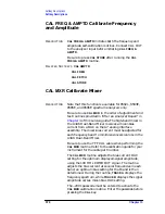
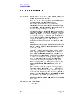
Note that the
CAL YTF
routine must be performed
before running the
CAL MXR
routine. New frequency
response correction constants must also be generated
whenever the
CAL MXR
routine is used. Refer to the
CAL MXR adjustment routine in
instructions on the use of the
CAL YTF
and
CAL MXR
routines.
Once the
CAL MXR
routine is finished, the optimum
bias-current value for each frequency band is displayed.
The displayed values are the mixer bias DAC setting
multiplied by 16. The DAC values are automatically
stored as correction constants in nonvolatile memory on
the A16 processor/video assembly.
R
ELATED
S
OFTKEYS
CAL YTF
EDIT FLATNESS
CAL STORE
Calibration Store
D
ESCRIPTION
CAL STORE
copies the correction factors from working
RAM to the area of memory on the A16 processor/video
assembly that retains data after the analyzer is turned
off.
CAUTION
If the correction factors are not stored, they will be lost when the
analyzer is turned off.
R
ELATED
S
OFTKEYS
CAL AMPTD
CAL FREQ
CAL FREQ & AMPTD
CAL FETCH
CAL TIMEBASE
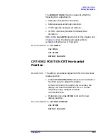
CRT VERT POSITION
CRT HORZ POSITION
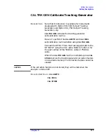
CAL TRK GEN
Summary of Contents for 8590L
Page 29: ...30 Chapter1 Introduction If You Replace or Repair an Assembly ...
Page 175: ...176 Chapter2 Making Adjustments 28 Correcting for Absolute Amplitude Accuracy for Option 051 ...
Page 279: ...280 Chapter5 Troubleshooting the IF Section Troubleshooting the A15 Motherboard Assembly ...
Page 347: ...348 Chapter7 Replacing Major Assemblies Rear Frame Assembly ...
Page 355: ...356 Chapter8 If You Have A Problem Returning Your Analyzer for Service ...
Page 379: ...380 Chapter9 Assembly Descriptions and Block Diagrams IF Section ...
Page 380: ......
Page 381: ...382 Chapter9 Assembly Descriptions and Block Diagrams IF Section ...
Page 382: ......
Page 383: ...384 Chapter9 Assembly Descriptions and Block Diagrams IF Section ...
Page 384: ......
Page 385: ...386 Chapter9 Assembly Descriptions and Block Diagrams IF Section ...
Page 386: ......
Page 387: ...388 Chapter9 Assembly Descriptions and Block Diagrams IF Section ...
Page 388: ......
Page 389: ...390 Chapter9 Assembly Descriptions and Block Diagrams IF Section ...
Page 390: ......
Page 391: ...392 Chapter9 Assembly Descriptions and Block Diagrams IF Section ...
Page 392: ...393 10 Analyzer Options and Block Diagrams ...
Page 443: ...444 Chapter10 Analyzer Options and Block Diagrams Option 190 DVB C Service Menus ...
Page 444: ......
Page 445: ...446 Chapter10 Analyzer Options and Block Diagrams Option 190 DVB C Service Menus ...
Page 446: ......
Page 447: ...448 Chapter10 Analyzer Options and Block Diagrams Option 190 DVB C Service Menus ...
Page 448: ......
Page 449: ...450 Chapter10 Analyzer Options and Block Diagrams Option 190 DVB C Service Menus ...
Page 451: ...452 Chapter10 Analyzer Options and Block Diagrams Option 190 DVB C Service Menus ...
Page 483: ...484 Chapter11 Major Assembly and Cable Locations Major Assembly and Cable Locations ...
Page 537: ...538 Chapter12 Replaceable Parts Component Level Information Packets ...
Page 538: ......
Page 539: ...540 Chapter12 Replaceable Parts Component Level Information Packets ...
Page 540: ......
Page 541: ...542 Chapter12 Replaceable Parts Component Level Information Packets ...
Page 542: ...FOLDOUT 12 3 8590L AND 8591E RF ASSEMBLY ...
Page 543: ...544 Chapter12 Replaceable Parts Component Level Information Packets ...
Page 544: ......
Page 545: ...546 Chapter12 Replaceable Parts Component Level Information Packets ...
Page 546: ......
Page 547: ...548 Chapter12 Replaceable Parts Component Level Information Packets ...
Page 548: ......
Page 549: ...550 Chapter12 Replaceable Parts Component Level Information Packets ...
Page 550: ......
Page 551: ...552 Chapter12 Replaceable Parts Component Level Information Packets ...
Page 665: ...666 Chapter15 Service Equipment and Tools Service Equipment and Tools ...
Page 666: ...667 16 Safety and Regulatory Information ...
Page 673: ...674 Chapter16 Safety and Regulatory Information Protection from Electrostatic Discharge ...


