10
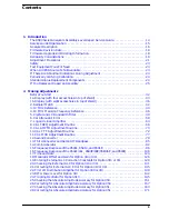
Contents
2a. Making Adjustments: If 3335A Source Not Available
Before You Start . . . . . . . . . . . . . . . . . . . . . . . . . . . . . . . . . . . . . . . . . . . . . . . . . . . . . . . . . . . .178
6a. Cal Attenuator Error . . . . . . . . . . . . . . . . . . . . . . . . . . . . . . . . . . . . . . . . . . . . . . . . . . . . .179
7a. Log and Linear Amplifier . . . . . . . . . . . . . . . . . . . . . . . . . . . . . . . . . . . . . . . . . . . . . . . . . .186
15a. Frequency Response of the 8590L, 8591C, and 8591E . . . . . . . . . . . . . . . . . . . . . . . . . .191
3. Backing Up and Reloading Correction Constants
Before You Start . . . . . . . . . . . . . . . . . . . . . . . . . . . . . . . . . . . . . . . . . . . . . . . . . . . . . . . . . . . .200
Backing Up Analyzer Correction Constants . . . . . . . . . . . . . . . . . . . . . . . . . . . . . . . . . . . . . .201
Analyzer Initialization . . . . . . . . . . . . . . . . . . . . . . . . . . . . . . . . . . . . . . . . . . . . . . . . . . . . . . .204
Reloading the Correction Constants . . . . . . . . . . . . . . . . . . . . . . . . . . . . . . . . . . . . . . . . . . . .207
Instrument Calibration after Reloading the Correction Constants . . . . . . . . . . . . . . . . . . . .209
4. Troubleshooting the Analyzer
Before You Start . . . . . . . . . . . . . . . . . . . . . . . . . . . . . . . . . . . . . . . . . . . . . . . . . . . . . . . . . . . .216
Problems at Instrument Power-Up . . . . . . . . . . . . . . . . . . . . . . . . . . . . . . . . . . . . . . . . . . . . .219
Troubleshooting an Inoperative Analyzer . . . . . . . . . . . . . . . . . . . . . . . . . . . . . . . . . . . . . . . .221
Troubleshooting the A2 Display Assembly . . . . . . . . . . . . . . . . . . . . . . . . . . . . . . . . . . . . . . .227
Isolating an RF, LO, IF, or Video Problem . . . . . . . . . . . . . . . . . . . . . . . . . . . . . . . . . . . . . . . .232
Using the Internal Service-Diagnostic Routines . . . . . . . . . . . . . . . . . . . . . . . . . . . . . . . . . .238
Troubleshooting the A16 Processor/Video Board Assembly . . . . . . . . . . . . . . . . . . . . . . . . . .249
5. Troubleshooting the IF Section
Before You Start . . . . . . . . . . . . . . . . . . . . . . . . . . . . . . . . . . . . . . . . . . . . . . . . . . . . . . . . . . . .254
Service Equipment You Will Need . . . . . . . . . . . . . . . . . . . . . . . . . . . . . . . . . . . . . . . . . . . . . .254
After an Analyzer Repair . . . . . . . . . . . . . . . . . . . . . . . . . . . . . . . . . . . . . . . . . . . . . . . . . . . . .255
IF Section Information . . . . . . . . . . . . . . . . . . . . . . . . . . . . . . . . . . . . . . . . . . . . . . . . . . . . . . .255
IF Power-Level Measurement . . . . . . . . . . . . . . . . . . . . . . . . . . . . . . . . . . . . . . . . . . . . . . . . .256
Troubleshooting the A15 Motherboard Assembly . . . . . . . . . . . . . . . . . . . . . . . . . . . . . . . . .266
6. Troubleshooting the RF Section
Before You Start . . . . . . . . . . . . . . . . . . . . . . . . . . . . . . . . . . . . . . . . . . . . . . . . . . . . . . . . . . . .282
Service Equipment You Will Need . . . . . . . . . . . . . . . . . . . . . . . . . . . . . . . . . . . . . . . . . . . . . .283
After an Analyzer Repair . . . . . . . . . . . . . . . . . . . . . . . . . . . . . . . . . . . . . . . . . . . . . . . . . . . . .283
6a. 8590L, 8591C, and 8591E . . . . . . . . . . . . . . . . . . . . . . . . . . . . . . . . . . . . . . . . . . . . . . . . .284
6b. 8592L/94L, 8594Q, and 8593E/94E/95E/96E . . . . . . . . . . . . . . . . . . . . . . . . . . . . . . . . . .287
Before You Start . . . . . . . . . . . . . . . . . . . . . . . . . . . . . . . . . . . . . . . . . . . . . . . . . . . . . . . . . . . .294
Service Equipment You Will Need . . . . . . . . . . . . . . . . . . . . . . . . . . . . . . . . . . . . . . . . . . . . . .294
After an Analyzer Repair . . . . . . . . . . . . . . . . . . . . . . . . . . . . . . . . . . . . . . . . . . . . . . . . . . . . .295
Removal and Replacement Procedures in this Chapter . . . . . . . . . . . . . . . . . . . . . . . . . . . . .295
Instrument Cover . . . . . . . . . . . . . . . . . . . . . . . . . . . . . . . . . . . . . . . . . . . . . . . . . . . . . . . . . . .296
A1 Front-Frame Assembly . . . . . . . . . . . . . . . . . . . . . . . . . . . . . . . . . . . . . . . . . . . . . . . . . . . .298
A1A1 Keyboard/Front-Panel Keys . . . . . . . . . . . . . . . . . . . . . . . . . . . . . . . . . . . . . . . . . . . . . .302
A2 Display . . . . . . . . . . . . . . . . . . . . . . . . . . . . . . . . . . . . . . . . . . . . . . . . . . . . . . . . . . . . . . . . .303
RF Assembly . . . . . . . . . . . . . . . . . . . . . . . . . . . . . . . . . . . . . . . . . . . . . . . . . . . . . . . . . . . . . . .308
A3 Front-End Assembly . . . . . . . . . . . . . . . . . . . . . . . . . . . . . . . . . . . . . . . . . . . . . . . . . . . . . .311
Summary of Contents for 8590L
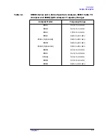
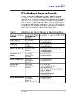
Page 29: ...30 Chapter1 Introduction If You Replace or Repair an Assembly ...
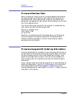
Page 175: ...176 Chapter2 Making Adjustments 28 Correcting for Absolute Amplitude Accuracy for Option 051 ...
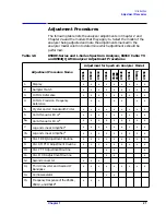
Page 279: ...280 Chapter5 Troubleshooting the IF Section Troubleshooting the A15 Motherboard Assembly ...
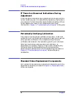
Page 347: ...348 Chapter7 Replacing Major Assemblies Rear Frame Assembly ...
Page 355: ...356 Chapter8 If You Have A Problem Returning Your Analyzer for Service ...
Page 379: ...380 Chapter9 Assembly Descriptions and Block Diagrams IF Section ...
Page 380: ......
Page 381: ...382 Chapter9 Assembly Descriptions and Block Diagrams IF Section ...
Page 382: ......
Page 383: ...384 Chapter9 Assembly Descriptions and Block Diagrams IF Section ...
Page 384: ......
Page 385: ...386 Chapter9 Assembly Descriptions and Block Diagrams IF Section ...
Page 386: ......
Page 387: ...388 Chapter9 Assembly Descriptions and Block Diagrams IF Section ...
Page 388: ......
Page 389: ...390 Chapter9 Assembly Descriptions and Block Diagrams IF Section ...
Page 390: ......
Page 391: ...392 Chapter9 Assembly Descriptions and Block Diagrams IF Section ...
Page 392: ...393 10 Analyzer Options and Block Diagrams ...
Page 443: ...444 Chapter10 Analyzer Options and Block Diagrams Option 190 DVB C Service Menus ...
Page 444: ......
Page 445: ...446 Chapter10 Analyzer Options and Block Diagrams Option 190 DVB C Service Menus ...
Page 446: ......
Page 447: ...448 Chapter10 Analyzer Options and Block Diagrams Option 190 DVB C Service Menus ...
Page 448: ......
Page 449: ...450 Chapter10 Analyzer Options and Block Diagrams Option 190 DVB C Service Menus ...
Page 451: ...452 Chapter10 Analyzer Options and Block Diagrams Option 190 DVB C Service Menus ...
Page 483: ...484 Chapter11 Major Assembly and Cable Locations Major Assembly and Cable Locations ...
Page 537: ...538 Chapter12 Replaceable Parts Component Level Information Packets ...
Page 538: ......
Page 539: ...540 Chapter12 Replaceable Parts Component Level Information Packets ...
Page 540: ......
Page 541: ...542 Chapter12 Replaceable Parts Component Level Information Packets ...
Page 542: ...FOLDOUT 12 3 8590L AND 8591E RF ASSEMBLY ...
Page 543: ...544 Chapter12 Replaceable Parts Component Level Information Packets ...
Page 544: ......
Page 545: ...546 Chapter12 Replaceable Parts Component Level Information Packets ...
Page 546: ......
Page 547: ...548 Chapter12 Replaceable Parts Component Level Information Packets ...
Page 548: ......
Page 549: ...550 Chapter12 Replaceable Parts Component Level Information Packets ...
Page 550: ......
Page 551: ...552 Chapter12 Replaceable Parts Component Level Information Packets ...
Page 665: ...666 Chapter15 Service Equipment and Tools Service Equipment and Tools ...
Page 666: ...667 16 Safety and Regulatory Information ...
Page 673: ...674 Chapter16 Safety and Regulatory Information Protection from Electrostatic Discharge ...


