Chapter 2
111
Making Adjustments
16. Frequency Response of the 8592L/94L, 8593E/94E/95E/96E, and 8594Q
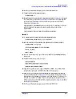
36.On the synthesized sweeper, press CW and STEP UP.
37.Press the following analyzer keys.
FREQUENCY,
⇑
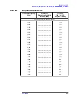
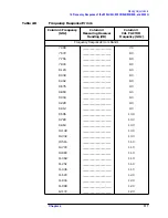
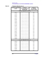
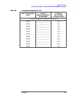
38.Step through the remaining frequencies listed in
. At each
new frequency, repeat
power sensor cal factor into the measuring receiver as listed in
Column 3 of
Adjustment for the 8596E spectrum analyzer is complete. Continue
with “Entering Flatness Correction Data” at the end of this
adjustment.
Continue with the next step for all other analyzers.
Band 3
39.To enter band 3, press the following analyzer keys.
FREQUENCY, BAND LOCK
,
12.4-19. BAND 3
40.Set the controls of the analyzer by pressing the following keys.
FREQUENCY
, 12.45,
GHz
CF STEP AUTO MAN
, (MAN) 230,
MHz
SPAN
, 10,
MHz
BW
, 1,
MHz
41.Set the synthesized sweeper CW to 12.45 GHz and FREQ STEP to
230 MHz.
42.Press the following analyzer keys.
PEAK SEARCH
MKR FCTN
,
MK TRACK ON OFF
(ON)
AMPLITUDE
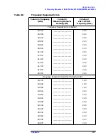
,
PRESEL PEAK
43.Adjust the synthesized sweeper POWER LEVEL for a MKR-TRK
amplitude reading of
−
20 dBm
±
0.1 dB on the analyzer.
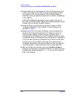
44.Add 11 dB to the power ratio displayed on the measuring receiver
and record the result in
. For example, if the power ratio
displayed on the measuring receiver is 6.7 dB, enter 17.7 dB (Error =
6.7 dB + 11.0 dB = 17.7 dB). The 11 dB correction comes from the
difference between the MKR-TRK amplitudes set in
(
−
9 dBm)
and
(
−
20 dBm).
45.On the synthesized sweeper, press CW and STEP UP.
Summary of Contents for 8590L
Page 29: ...30 Chapter1 Introduction If You Replace or Repair an Assembly ...
Page 175: ...176 Chapter2 Making Adjustments 28 Correcting for Absolute Amplitude Accuracy for Option 051 ...
Page 279: ...280 Chapter5 Troubleshooting the IF Section Troubleshooting the A15 Motherboard Assembly ...
Page 347: ...348 Chapter7 Replacing Major Assemblies Rear Frame Assembly ...
Page 355: ...356 Chapter8 If You Have A Problem Returning Your Analyzer for Service ...
Page 379: ...380 Chapter9 Assembly Descriptions and Block Diagrams IF Section ...
Page 380: ......
Page 381: ...382 Chapter9 Assembly Descriptions and Block Diagrams IF Section ...
Page 382: ......
Page 383: ...384 Chapter9 Assembly Descriptions and Block Diagrams IF Section ...
Page 384: ......
Page 385: ...386 Chapter9 Assembly Descriptions and Block Diagrams IF Section ...
Page 386: ......
Page 387: ...388 Chapter9 Assembly Descriptions and Block Diagrams IF Section ...
Page 388: ......
Page 389: ...390 Chapter9 Assembly Descriptions and Block Diagrams IF Section ...
Page 390: ......
Page 391: ...392 Chapter9 Assembly Descriptions and Block Diagrams IF Section ...
Page 392: ...393 10 Analyzer Options and Block Diagrams ...
Page 443: ...444 Chapter10 Analyzer Options and Block Diagrams Option 190 DVB C Service Menus ...
Page 444: ......
Page 445: ...446 Chapter10 Analyzer Options and Block Diagrams Option 190 DVB C Service Menus ...
Page 446: ......
Page 447: ...448 Chapter10 Analyzer Options and Block Diagrams Option 190 DVB C Service Menus ...
Page 448: ......
Page 449: ...450 Chapter10 Analyzer Options and Block Diagrams Option 190 DVB C Service Menus ...
Page 451: ...452 Chapter10 Analyzer Options and Block Diagrams Option 190 DVB C Service Menus ...
Page 483: ...484 Chapter11 Major Assembly and Cable Locations Major Assembly and Cable Locations ...
Page 537: ...538 Chapter12 Replaceable Parts Component Level Information Packets ...
Page 538: ......
Page 539: ...540 Chapter12 Replaceable Parts Component Level Information Packets ...
Page 540: ......
Page 541: ...542 Chapter12 Replaceable Parts Component Level Information Packets ...
Page 542: ...FOLDOUT 12 3 8590L AND 8591E RF ASSEMBLY ...
Page 543: ...544 Chapter12 Replaceable Parts Component Level Information Packets ...
Page 544: ......
Page 545: ...546 Chapter12 Replaceable Parts Component Level Information Packets ...
Page 546: ......
Page 547: ...548 Chapter12 Replaceable Parts Component Level Information Packets ...
Page 548: ......
Page 549: ...550 Chapter12 Replaceable Parts Component Level Information Packets ...
Page 550: ......
Page 551: ...552 Chapter12 Replaceable Parts Component Level Information Packets ...
Page 665: ...666 Chapter15 Service Equipment and Tools Service Equipment and Tools ...
Page 666: ...667 16 Safety and Regulatory Information ...
Page 673: ...674 Chapter16 Safety and Regulatory Information Protection from Electrostatic Discharge ...


