Chapter 2
155
Making Adjustments
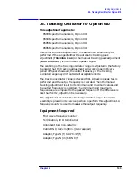
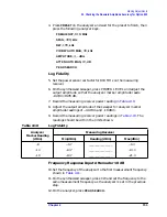
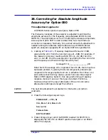
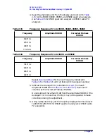
25. Checking the Absolute Amplitude Accuracy for Option 050
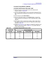
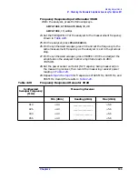
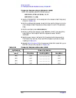
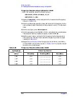
Frequency Response Input Attenuator 30 dB
23.On the analyzer, press the following keys.
AMPLITUDE, ATTEN AUTO MAN
, 30, dB
AMPLITUDE
, 10,
+dBm
24.Set the FREQUENCY of the analyzer to the measurement frequency
shown in
25.On the analyzer, press
PEAK SEARCH
.
26.On the synthesized sweeper, press CW and set the frequency to the
same measurement frequency as the analyzer is set in the previous
step.
27.On the synthesized sweeper, press POWER LEVEL and adjust the
amplitude so the analyzer marker amplitude reads
+5 dBm
±
0.05 dB.
28.Set the power sensor cal factor (for frequency being measured) on
the measuring receiver, then record the measuring receiver power
reading in
.
29.Repeat
to
for frequencies of 836 MHz, 881 MHz, and
948 MHz. Record the results in
.
Table 2-12
Frequency Response Attenuator 20 dB
Synthesized
Sweeper Frequency
(MHz)
Measuring Receiver
Min (dBm)
Reading (dBm)
Max (dBm)
948
+0.3
_________________
+1.7
881
+0.3
_________________
+1.7
836
+0.3
_________________
+1.7
818
+0.3
_________________
+1.7
Table 2-13
Frequency Response Attenuator 30 dB
Synthesized
Sweeper Frequency
(MHz)
Measuring Receiver
Min (dBm)
Reading (dBm)
Max (dBm)
818
+4.3
_________________
+5.7
836
+4.3
_________________
+5.7
881
+4.3
_________________
+5.7
948
+4.3
_________________
+5.7
Summary of Contents for 8590L
Page 29: ...30 Chapter1 Introduction If You Replace or Repair an Assembly ...
Page 175: ...176 Chapter2 Making Adjustments 28 Correcting for Absolute Amplitude Accuracy for Option 051 ...
Page 279: ...280 Chapter5 Troubleshooting the IF Section Troubleshooting the A15 Motherboard Assembly ...
Page 347: ...348 Chapter7 Replacing Major Assemblies Rear Frame Assembly ...
Page 355: ...356 Chapter8 If You Have A Problem Returning Your Analyzer for Service ...
Page 379: ...380 Chapter9 Assembly Descriptions and Block Diagrams IF Section ...
Page 380: ......
Page 381: ...382 Chapter9 Assembly Descriptions and Block Diagrams IF Section ...
Page 382: ......
Page 383: ...384 Chapter9 Assembly Descriptions and Block Diagrams IF Section ...
Page 384: ......
Page 385: ...386 Chapter9 Assembly Descriptions and Block Diagrams IF Section ...
Page 386: ......
Page 387: ...388 Chapter9 Assembly Descriptions and Block Diagrams IF Section ...
Page 388: ......
Page 389: ...390 Chapter9 Assembly Descriptions and Block Diagrams IF Section ...
Page 390: ......
Page 391: ...392 Chapter9 Assembly Descriptions and Block Diagrams IF Section ...
Page 392: ...393 10 Analyzer Options and Block Diagrams ...
Page 443: ...444 Chapter10 Analyzer Options and Block Diagrams Option 190 DVB C Service Menus ...
Page 444: ......
Page 445: ...446 Chapter10 Analyzer Options and Block Diagrams Option 190 DVB C Service Menus ...
Page 446: ......
Page 447: ...448 Chapter10 Analyzer Options and Block Diagrams Option 190 DVB C Service Menus ...
Page 448: ......
Page 449: ...450 Chapter10 Analyzer Options and Block Diagrams Option 190 DVB C Service Menus ...
Page 451: ...452 Chapter10 Analyzer Options and Block Diagrams Option 190 DVB C Service Menus ...
Page 483: ...484 Chapter11 Major Assembly and Cable Locations Major Assembly and Cable Locations ...
Page 537: ...538 Chapter12 Replaceable Parts Component Level Information Packets ...
Page 538: ......
Page 539: ...540 Chapter12 Replaceable Parts Component Level Information Packets ...
Page 540: ......
Page 541: ...542 Chapter12 Replaceable Parts Component Level Information Packets ...
Page 542: ...FOLDOUT 12 3 8590L AND 8591E RF ASSEMBLY ...
Page 543: ...544 Chapter12 Replaceable Parts Component Level Information Packets ...
Page 544: ......
Page 545: ...546 Chapter12 Replaceable Parts Component Level Information Packets ...
Page 546: ......
Page 547: ...548 Chapter12 Replaceable Parts Component Level Information Packets ...
Page 548: ......
Page 549: ...550 Chapter12 Replaceable Parts Component Level Information Packets ...
Page 550: ......
Page 551: ...552 Chapter12 Replaceable Parts Component Level Information Packets ...
Page 665: ...666 Chapter15 Service Equipment and Tools Service Equipment and Tools ...
Page 666: ...667 16 Safety and Regulatory Information ...
Page 673: ...674 Chapter16 Safety and Regulatory Information Protection from Electrostatic Discharge ...


