background image

3-15

Using the Analyzer

Measurement Techniques

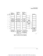
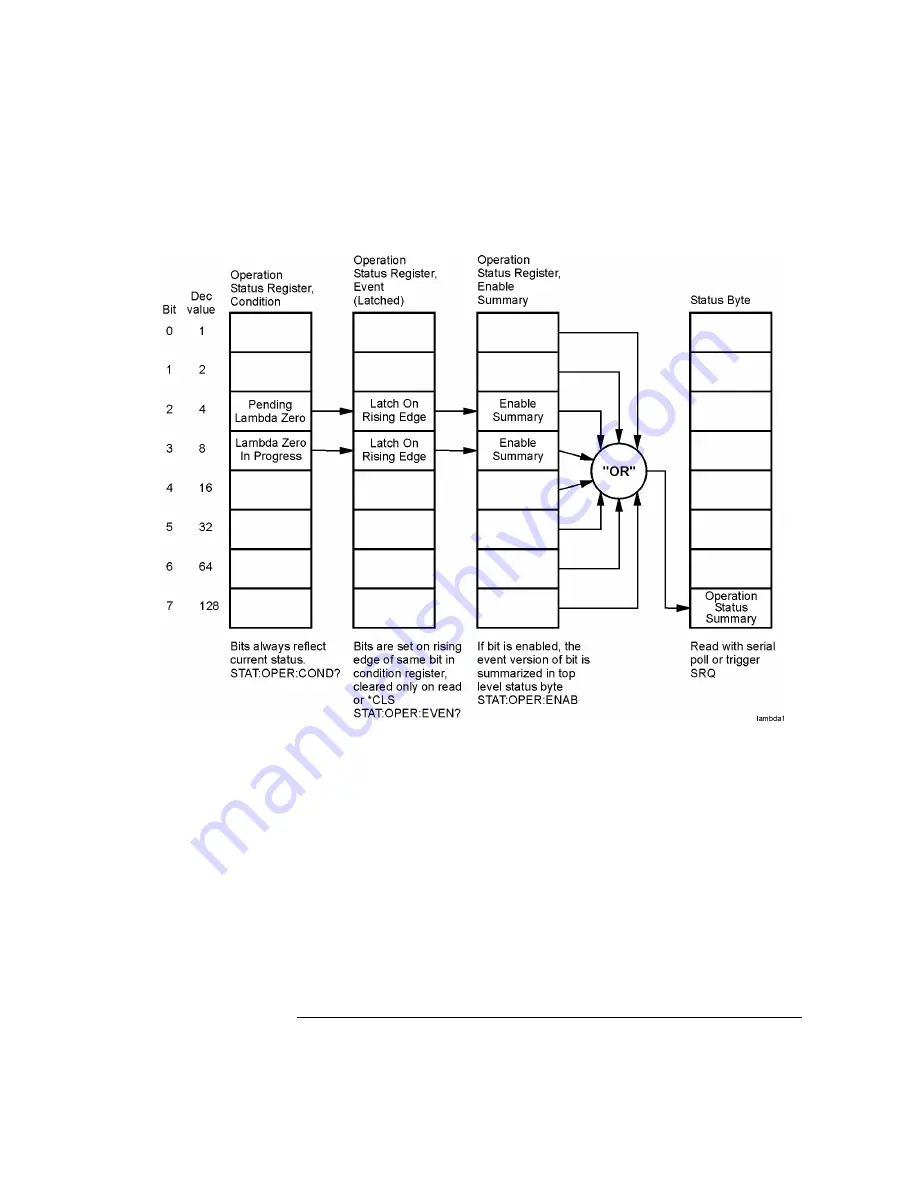
Figure 3-3. Lambda Zero Status Bit Registers 

Artisan Technology Group - Quality Instrumentation ... Guaranteed | (888) 88-SOURCE | www.artisantg.com

Summary of Contents for 86082A

Page 1: ...l service in house repair center WE BUY USED EQUIPMENT Sell your excess underutilized and idle used equipment We also offer credit for buy backs and trade ins www artisantg com WeBuyEquipment REMOTE INSPECTION Remotely inspect equipment before purchasing with our interactive website at www instraview com LOOKING FOR MORE INFORMATION Visit us on the web at www artisantg com for more information on ...

Page 2: ...Agilent 86082A Wavelength Domain Component Analyzer User s Guide Artisan Technology Group Quality Instrumentation Guaranteed 888 88 SOURCE www artisantg com ...

Page 3: ...ce by Buyer Buyer supplied software or interfac ing unauthorized modifica tion or misuse operation outside of the environmental specifications for the product or improper site preparation or maintenance No other warranty is expressed or implied Agilent Technologies specifically dis claims the implied warranties of merchantability and fitness for a particular purpose Exclusive Remedies The remedies...

Page 4: ...do not remove covers WAR N I N G This is a Safety Class 1 Product provided with a protective earthing ground incorporated in the power cord The mains plug shall only be inserted in a socket outlet provided with a protective earth contact Any interruption of the protective conductor inside or outside of the instrument is likely to make the instrument dangerous Intentional interruption is prohibited...

Page 5: ...er cord is the instrument disconnecting device It disconnects the mains circuit from the mains supply before other parts of the instrument The front panel switch is only a standby switch and is not a LINE switch Alternatively an externally installed switch or circuit breaker which is readily identifiable and is easily reached by the operator may be used as a disconnecting device C AUT IO N Always ...

Page 6: ...h Menu 1 30 Laser Safety Considerations 1 31 Setting Up the WDCA 1 32 To Learn More About Agilent Products 1 37 2 Function Reference 3 Using the Analyzer The Basics 3 2 To Fill In a Setup Panel 3 2 Adding a Title to the Display 3 3 Backing Up or Restoring the Internal Memory 3 4 Moving the Active Function Area 3 4 Saving Measurement and Trace Data 3 5 Entering a Filename Using the Arrow Keys 3 7 E...

Page 7: ...Trace Math to Measure Wavelength Drift 3 41 4 Remote Front Panel Operation Remote Front Panel 4 2 Information and Equipment Required for the Configuration Process 4 2 Setting Up the Analyzer for Remote Operation 4 4 Connecting to the Analyzer over the Network 4 6 Using the Reflection X Emulator to Run the Remote Front Panel 4 7 Using the X Win 32 Emulator to Run the Remote Front Panel 4 9 Using a ...

Page 8: ... Subsystem Commands 6 73 HCOPy Subsystem Commands 6 74 INITiate Subsystem Commands 6 76 MEMory Subsystem Commands 6 78 MMEMory Subsystem Commands 6 79 OUTPut Subsystem Commands 6 82 SENSe Subsystem Commands 6 83 STATus Subsystem Commands 6 91 SYSTem Subsystem Commands 6 96 TRACe Subsystem Commands 6 101 UNIT Subsystem Commands 6 107 Agilent 86140B Series Command Compatibility to Agilent 86082A Ser...

Page 9: ... 8 7 Cleaning Connections for Accurate Measurements 8 11 Choosing the Right Connector 8 11 Inspecting Connectors 8 14 Cleaning Connectors 8 18 Care of Connector Savers 8 21 Cleaning Connector Savers 8 22 Returning the Instrument for Service 8 24 Preparing the Instrument for Shipping 8 26 Agilent Technologies Service Offices 8 28 9 Specifications and Regulatory Information Definition of Terms 9 3 S...

Page 10: ...Contents 5 Contents Regulatory Information 9 14 Declaration of Conformity 9 15 Artisan Technology Group Quality Instrumentation Guaranteed 888 88 SOURCE www artisantg com ...

Page 11: ...Contents 6 Contents Artisan Technology Group Quality Instrumentation Guaranteed 888 88 SOURCE www artisantg com ...

Page 12: ...c Adapters 1 9 Agilent 86082A Front and Rear Panels 1 10 WDCA Display 1 13 Accessing the WDCA Functions 1 15 The Menu Bar 1 16 The Softkey Panels 1 18 Laser Safety Considerations 1 31 Setting Up the WDCA 1 32 Getting Started Artisan Technology Group Quality Instrumentation Guaranteed 888 88 SOURCE www artisantg com ...

Page 13: ... precision and fast measurement speeds necessary for these demanding measurements Instrument features The WDCA combines the best of Agilent Technologies optical spectrum ana lyzer OSA and tunable laser source TLS The receiver in the 86082A has the dynamic range digital signal processing large display feature set and graphical user interface of Agilent s OSA This receiver is integrated with Agi len...

Page 14: ...e filter s insertion loss and pass band location Range lock is available with any of the performance modes With the WDCA you can make stimulus response measurements without the use of external programs controllers or programming Because it is an inte grated system there is no concern with linking and synchronizing the source and receiver Manual users will find the features interface and large disp...

Page 15: ...ver 86082 40002 1 FC PC FC APC SM OC 0 3 M Normalization Optical Cable 1005 0954 1 FC PC FC APC SM OC 1 0 M Wavelength Reference Cable 1005 0953 1 FC PC Connector Adapter 08154 61702 2 Angled to Flat Connector Converter 1005 0089 1 FC PC Dust Cap 1401 0291 2 English User s Guide Manual 86082 90001 1 Quick Start Card 86082 90005 1 CD ROM 86082 90004 1 Artisan Technology Group Quality Instrumentatio...

Page 16: ...at FC PC Adapter 08154 61702 1401 0291 1250 3175 3 3 1 013 DIN Optical Connector Adapter DIN Dust Cap 08154 61703 1401 0291 3 3 014 ST Optical Connector Adapter ST Dust Cap 08154 61704 1401 0291 3 3 017 SC Optical Connector Adapter SC Dust Cap 08154 61708 1401 0291 3 3 Reference Reflector 81000BR Power Selection 900 Power Cord United Kingdom 8120 8705 1 901 Power Cord Australia New Zealand China 8...

Page 17: ... 1 Documentation and Manuals ABA English User s Guide Service Guide English CD ROM Manual Set Quick Start 86082 90001 86082 90002 86082 90004 86082 90005 1 ABJ Japanese User s Guide 86082 90006 1 AB2 Simplified Chinese User s Guide 86082 90007 1 Certification of Calibration 1BM Standard Commercial Calibration Certificate 1 UK6 Commercial Calibration Certificate with Test Data N A 1 Option Descript...

Page 18: ...1521 Straight NEMA5 15P 90 90 228 90 228 Jade Gray Jade Gray United States Canada Mexico Philippines Taiwan 250V 8120 2104C 8120 2296 Straight SEV1011 1959 24507 Type 12 90 79 200 79 200 Mint Gray Mint Gray Switzerland 220V 8120 2956C 8120 2957 Straight DHCK107 90 79 200 79 200 Mint Gray Mint Gray Denmark 250V 8120 4211 8120 4600 Straight SABS164 90 79 200 79 200 Jade Gray Republic of South Africa...

Page 19: ...t No Plug Description Length in cm Color Country Part number shown for plug is the industry identifier for the plug only Number shown for cable is the Agilent part number for the complete cable including the plug Artisan Technology Group Quality Instrumentation Guaranteed 888 88 SOURCE www artisantg com ...

Page 20: ...Optic Adapter Description Agilent Part Number Diamond HMS 10 08154 61701 FC PCa a The FC PC is the default front panel optical connector 08154 61702 SC 08154 61708 DIN 08154 61703 ST 08154 61704 Biconic 08154 61705 Artisan Technology Group Quality Instrumentation Guaranteed 888 88 SOURCE www artisantg com ...

Page 21: ...1 10 Getting Started Agilent 86082A Front and Rear Panels Agilent 86082A Front and Rear Panels Artisan Technology Group Quality Instrumentation Guaranteed 888 88 SOURCE www artisantg com ...

Page 22: ...1 11 Getting Started Agilent 86082A Front and Rear Panels Figure 1 1 Front Panel Artisan Technology Group Quality Instrumentation Guaranteed 888 88 SOURCE www artisantg com ...

Page 23: ...1 12 Getting Started Agilent 86082A Front and Rear Panels Figure 1 2 Rear Panel Artisan Technology Group Quality Instrumentation Guaranteed 888 88 SOURCE www artisantg com ...

Page 24: ...1 13 Getting Started WDCA Display WDCA Display Figure 1 3 WDCA Display Artisan Technology Group Quality Instrumentation Guaranteed 888 88 SOURCE www artisantg com ...

Page 25: ...1 14 Getting Started WDCA Display Figure 1 4 Display Annotations Artisan Technology Group Quality Instrumentation Guaranteed 888 88 SOURCE www artisantg com ...

Page 26: ...ctions Accessing the WDCA Functions Instrument settings can be accessed from either the menu bar or the softkey panel Figure 1 5 Accessing WDCA Functions Artisan Technology Group Quality Instrumentation Guaranteed 888 88 SOURCE www artisantg com ...

Page 27: ...election includes a descriptive label Access to the Menu bar is accomplished with either a mouse or keyboard You must restart the WDCA after installing a mouse or keyboard to activate File Menu Measure Menu Applications Menu Not used at this time Artisan Technology Group Quality Instrumentation Guaranteed 888 88 SOURCE www artisantg com ...

Page 28: ...1 17 Getting Started The Menu Bar Options Menu Artisan Technology Group Quality Instrumentation Guaranteed 888 88 SOURCE www artisantg com ...

Page 29: ...ions of the following menus See Chap ter 2 Function Reference for additional information on each of the analyzer functions The Amplitude Menus 1 19 The Markers Menus 1 20 The Save Recall Menus 1 23 The Sweep Menu 1 24 The System Menus 1 26 The Traces Menus 1 28 The Wavelength Menu 1 30 Artisan Technology Group Quality Instrumentation Guaranteed 888 88 SOURCE www artisantg com ...

Page 30: ...The Amplitude Menus The Amplitude softkeys are accessed by using the front panel Amplitude key or the Measure menu Amplitude selection on the menu bar Artisan Technology Group Quality Instrumentation Guaranteed 888 88 SOURCE www artisantg com ...

Page 31: ...nels The Markers Menus The Markers softkeys are accessed using the front panel Markers key or the Measure menu Markers selection on the menu bar Artisan Technology Group Quality Instrumentation Guaranteed 888 88 SOURCE www artisantg com ...

Page 32: ...1 21 Getting Started The Softkey Panels Artisan Technology Group Quality Instrumentation Guaranteed 888 88 SOURCE www artisantg com ...

Page 33: ...The Norm Ref softkey and setup panels are accessed by using the drop down Measure menu Norm Ref selection from the front panel Norm Ref key or from the front panel Amplitude Norm Ref Artisan Technology Group Quality Instrumentation Guaranteed 888 88 SOURCE www artisantg com ...

Page 34: ...eys and setup panels are accessed by using the drop down File menu Save Recall selection or the front panel Save Recall key Use these functions to save recall and print the measurement results Artisan Technology Group Quality Instrumentation Guaranteed 888 88 SOURCE www artisantg com ...

Page 35: ...y Panels The Sweep Menu The Sweep softkeys are accessed using the front panel Sweep key or the Mea sure menu Sweep selection on the menu bar Artisan Technology Group Quality Instrumentation Guaranteed 888 88 SOURCE www artisantg com ...

Page 36: ...1 25 Getting Started The Softkey Panels This page left intentionally blank Artisan Technology Group Quality Instrumentation Guaranteed 888 88 SOURCE www artisantg com ...

Page 37: ...Panels The System Menus The System softkeys are accessed using the front panel System key or the Options menu System selection on the menu bar Artisan Technology Group Quality Instrumentation Guaranteed 888 88 SOURCE www artisantg com ...

Page 38: ...1 27 Getting Started The Softkey Panels Artisan Technology Group Quality Instrumentation Guaranteed 888 88 SOURCE www artisantg com ...

Page 39: ...anels The Traces Menus The Traces softkeys are accessed by using the front panel Traces key or the Measure menu Traces selection on the menu bar Artisan Technology Group Quality Instrumentation Guaranteed 888 88 SOURCE www artisantg com ...

Page 40: ...1 29 Getting Started The Softkey Panels Artisan Technology Group Quality Instrumentation Guaranteed 888 88 SOURCE www artisantg com ...

Page 41: ...The Wavelength Menu The Wavelength softkeys are accessed using the front panel Wavelength key or the Measure menu Wavelength selection on the menu bar Artisan Technology Group Quality Instrumentation Guaranteed 888 88 SOURCE www artisantg com ...

Page 42: ...put or any fiber device attached to the output while the laser is in operation This system should be serviced only by authorized personnel Do not enable the laser unless fiber or an equivalent device is attached to the optical output connector C AUT IO N Use of controls or adjustments or performance of procedures other than those specified herein can result in hazardous radiation exposure Electric...

Page 43: ...DCA Shipment Contents 1 Unpack your shipment Inspect the shipping containers for damage Inspect the instrument s Verify that you received the options and accessories that you ordered Artisan Technology Group Quality Instrumentation Guaranteed 888 88 SOURCE www artisantg com ...

Page 44: ...will arrange for repair or replacement at Agilent Technologies option without waiting for a claim settlement Refer to Returning the Instrument for Service on page 8 24 C AUT IO N Fiber optic connectors are easily damaged when connected to dirty or damaged cables and accessories When you use improper cleaning and handling techniques you risk expensive instrument repairs damaged cables and compromis...

Page 45: ...1 34 Getting Started Setting Up the WDCA Figure 1 7 Front Panel Configuration Artisan Technology Group Quality Instrumentation Guaranteed 888 88 SOURCE www artisantg com ...

Page 46: ...tting Up the WDCA Figure 1 8 Rear Panel Configuration 3 Turn on both instruments The start up process takes approximately 15 minutes Artisan Technology Group Quality Instrumentation Guaranteed 888 88 SOURCE www artisantg com ...

Page 47: ...ngth calibration by pressing System Wavelength Calibration Perform Calibration The calibration takes approximately 5 minutes 6 Normalize Receiver Input 1 by pressing Norm Ref Normalize Input 1 7 When the normalization is complete the software automatically takes a sweep 8 Verify that the normalized trace is at 0 dB You are now ready to start making measurements Continue with Using the Analyzer on ...

Page 48: ...ic test equipment go to the Agilent Technologies home page listed above and follow this path 1 Click Communications 2 Click Optical and Photonic Solutions This path will take you to the Optical and Photonic Solutions page Alter nately you can enter the URL for this page directly http www agilent com cm opticalgrp shtml Artisan Technology Group Quality Instrumentation Guaranteed 888 88 SOURCE www a...

Page 49: ...1 38 Getting Started Setting Up the WDCA Artisan Technology Group Quality Instrumentation Guaranteed 888 88 SOURCE www artisantg com ...

Page 50: ...2 Function Reference Artisan Technology Group Quality Instrumentation Guaranteed 888 88 SOURCE www artisantg com ...

Page 51: ...ithout pressing the Center WL softkey If this function is off the active dialog box will not appear on the display To access the individ ual dialog box press the desired softkey function Key Path System More System Functions Display Setup Related Functions Move Active Area Active Marker Accesses a menu to select an active marker Selecting a marker always places that marker on the currently selecte...

Page 52: ...turned on Active normalized traces are indicated with a The scale on the right side of the display is for non normalized traces and will only be displayed when at least one active trace is non normalized Active non normalized traces are indicated with a In the event that there is at least one normalized trace and one non normalized trace both amplitude scales with be displayed on the screen See Ge...

Page 53: ...en this function is on the Agilent logo appears on the display s upper left corner of the graticule and on printouts Key Path System More System Functions Display Setup All Math Off Turns all the math functions off Key Path Traces More Trace Functions Trace Math Off All Math Off All Off Turns all the active markers off Key Path Markers Active Marker All Off Remote Commands CALCulate 1 2 3 4 5 6 MA...

Page 54: ...10 of the input signal at the top of the screen Key Path Amplitude Amplitude Setup Amp Display Mode Related Functions Amplitude Units Remote Commands DISPlay WINDow TRACe Y SCALe LINear Amplitude Accesses a menu of keys that control the analyzer s sensitivity and amplitude scales The Amplitude functions can be accessed from the front panel Ampli tude key or from the Measure menu Amplitude selectio...

Page 55: ...e logarithmic scale and in watts when using the linear scale Selecting W forces the readout to be in watts regardless of the amplitude scaling N o t e There are two amplitude scales that can be viewed on the WDCA The scale on the left side of the display is for normalized traces and will only be displayed when at least one active trace has normalization turned on Active normalized traces are indic...

Page 56: ...ormalization On Off Related Functions Normalize Input 1 Normalize Setup Remote Commands SENSe NORMalize ENABle SENSe NORMalize ENABle Apply Input 2 Normalization On Off Turns the trace normalization for Receiver Input 1 on or off Refer to Normal izing the Measurement on page 3 11 Key Path Norm Ref Apply Input 2 Normalization On Off Related Functions Normalize Input 2 Normalize Setup Remote Command...

Page 57: ...tive trace to Receiver Input 2 You can assign up to six traces to one input For example you may choose to assign three traces to input 2 Trace A could have View on but Update turned off Trace B could have Update on with Max Hold on Trace C could have Update and View on Key Path Traces Trace Input A Attach TRA to Input 2 Related Functions View trace Update trace Remote Commands TRACe FEED INPut TRA...

Page 58: ...ey Path Amplitude Amplitude Setup Auto Range Auto Zero Amplitude Setup Panel Turns Auto Zero on and off Auto Zero on enables the internal amplifiers to be zeroed between sweeps In this mode the analyzer compensates for tempera ture related current drift between each sweep Although this zeroing increases amplitude accuracy it also increases the time between sweeps If amplitude accuracy is not criti...

Page 59: ...rnal Memory Accesses the analyzer backup utility A screen appears asking you to insert a formatted floppy disk into the floppy drive The existing contents of the inter nal memory is then saved on the disk The Backup Internal Memory function overwrites the floppy disk with a new image Any existing files or catalogs on the floppy disk will be destroyed The disk will not be viewable on a PC and no tr...

Page 60: ...en the NDB value For positive NDB values the bandwidth markers will be at values clos est to and more positive than the NDB values This will typically result in a wider bandwidth measurement Key Path Markers Marker Setup Bandwidth Marker Interpolation Related Functions Active Marker Delta Marker Remote Commands CALCulate 1 2 3 4 5 6 MARKer 1 2 3 4 FUNCtion BANDwidth INTerpolation BW Marker Units M...

Page 61: ... as follows Key Path Wavelength Center WL Related Functions Start WL Stop WL Span Remote Commands SENSe WAVelength CENTer Center Wavelength Step Size Wavelength Setup Panel Specifies the center wavelength step size This is used for incrementing center wavelength using the and keys Key Path Wavelength Wavelength Setup Center Wavelength Step Size Remote Commands SENSe WAVelength CENTer STEP INCRemen...

Page 62: ... to enter the new GPIB address information in the Remote Setup panel Key Path System More System Functions Remote Setup Default Math Trace C Defines the math expression to be used and turns the math operation on C ALOG B C ALOG B C ALIN B or C ALIN B The result is placed in Trace C The math operation is performed in linear units See Upper and lower limit lines showing pass fail test on page 3 39 a...

Page 63: ...ces More Trace Functions Trace Math Off Default Math Trace F Remote Commands CALCulate6 MATH STATE OFF ON 0 1 Delete File From Delete Setup Panel Selects whether to delete a file from a floppy disk or from internal memory Key Path Save Recall Delete Menu Delete File From Remote Commands MMEMory DELete Delete Menu Accesses the Delete Setup panel This is used to delete files from a floppy disk or fr...

Page 64: ...arkers More Marker Functions Delta Marker Remote Commands CALCulate 1 2 3 4 5 6 MARKer 1 2 3 4 FUNCtion DELTa STATe Delta Marker Units Marker Setup Panel Sets the delta marker X axis readout for frequency or wavelength when the instrument is in a non zero span The available selections are nm µm Ang GHz and THz The default units are nm nanometers This setting controls all four delta markers The nor...

Page 65: ...Exchange Menu Accesses the exchange selections which include A Exchange B B Exchange C C Exchange A D Exchange A E Exchange A F Exchange A Exchanges the X and Y axis data of the two traces The only trace pairs that can be exchanged are Trace A with any trace and Trace B with Trace C Key Path Traces More Trace Functions Trace Math Exchange Menu Remote Commands TRACe EXCHange Artisan Technology Grou...

Page 66: ...n settings to original factory values and will clear the optional settings See Preset on page 2 44 Key Path System More System Functions Service Menu Factory Preset IP Related Functions Preset Fast Meas Recall Accesses the Fast Measure Recall function to recall the measurement state previously saved as FASTSAVE dat by the Fast Measure Save function Key Path Save Recall Fast Meas Recall Related Fun...

Page 67: ...e appropriate to use if the filter has very sharp responses The fast sweeping speed may not accurately display the signal N o t e The sweep time ST that is displayed in the lower portion of the display is the time for the WDCA to sweep over one gain stage The WDCA may take up to three sweeps in three different gain stages to make the measurement This depends on the settings for sensitivity referen...

Page 68: ...s a numbering system which is incremented each time the measurement data is saved For example the first time you save Trace s only data the filename TR_00001 csv will be assigned When Manual is selected pressing the Choose File to Save softkey will access the File Name Menu setup panel Use the front panel step keys and arrow softkeys to highlight and then select each letter in the filename When yo...

Page 69: ...strument firmware Refer to the CD ROM which was included with your shipment or to the web site below for upgrade instructions Key Path System More System Functions Service Menu Firmware Upgrade Remote Commands MMEMory INITialize Artisan Technology Group Quality Instrumentation Guaranteed 888 88 SOURCE www artisantg com ...

Page 70: ...nt amplitude value of each point on the active trace in the current sweep to the corresponding point detected during the previous sweep then displays the maximum value Hold Min compares the current amplitude value of each point on a trace in the current sweep to the corresponding point detected during the previous sweep then displays the minimum value Hold None turns the Hold function off Key Path...

Page 71: ... limit line 2 as a margin See Creating a Limit Line to Establish Pass Fail Criteria on page 3 36 Key Path Amplitude Limit Lines Limit Line Tests 1 2 Both Off Related Functions Load Limit Lines Remote Commands CALCulate 1 2 3 4 5 6 LLINe 1 2 DISPlay CALCulate 1 2 3 4 5 6 LLINe 1 2 FAIL CALCulate 1 2 3 4 5 6 LLINe 1 2 STATe MMEMory LOAD LLINE 1 2 file_name INTernal FLOPpy Lin Math C A B Subtracts Tr...

Page 72: ... Default Math Trace C Lin Math C A B Remote Commands CALCulate3 MATH EXPRession TRA TRB Line Markers Off Turns off all line markers and line marker functions Key Path Markers More Marker Functions Line Marker Menu Line Markers Off Remote Commands CALCulate 1 2 3 4 5 6 MARKer 1 2 3 4 SRANge OFF Load Limit Line 1 2 Allows you to select from the available limit lines for limit line testing Each limit...

Page 73: ... to Establish Pass Fail Criteria on page 3 36 for addi tional information Tip When choosing a file name you may want to indicate the limit line as either upper or lower Try to limit the file name to eight characters as only eight characters will be displayed in the Limit Line Catalog Key Path Amplitude Limit Lines Load Limit Lines Load Limit Line 1 Related Functions Limit Line Test 1 2 Both Off Re...

Page 74: ...ubtracts Trace B from Trace A point by point then stores the results in Trace C in logarithmic units If Trace A is in View On mode this function is continu ous and occurs every sweep Results of the subtraction are referenced to 0 dB This often requires a reference level adjustment For example if the reference level is set at 40 dBm Trace A is at 50 dBm and Trace B is at 55 dBm the C A B function p...

Page 75: ...ace D from Trace C point by point then stores the results in Trace F in logarithmic units If Trace C is in View On mode this function is continu ous and occurs every sweep Results of the subtraction are referenced to 0 dB This often requires a reference level adjustment For example if the reference level is set at 40 dBm Trace D is at 50 dBm and Trace C is at 55 dBm the F C D function places Trace...

Page 76: ...n of a response on page 3 21 Key Path Markers More Marker Functions Marker BW Related Functions Peak Search Remote Commands Marker BW On Off CALCulate 1 2 3 4 5 6 MARKer 1 2 3 4 FUNCtion BANDwidth STATe CALCulate 1 2 3 4 5 6 MARKer 1 2 3 4 FUNCtion BANDwidth INTerpolate 0 5 dB 3 dB 6 dB 10 dB 20 dB CALCulate 1 2 3 4 5 6 MARKer 1 2 3 4 FUNCtion BWIDwidth NDB CALCulate 1 2 3 4 5 6 MARKer 1 2 3 4 FUN...

Page 77: ... the threshold value will be ignored When the Marker Search Threshold is on a dotted line is shown on the display at the threshold level The Use Marker Search Threshold function in the Marker Setup Panel must be enabled or the Marker Search Threshold Value will be greyed out Key Path Markers Marker Setup Marker Search Threshold Value Related Functions Pit Excursion Peak Excursion Marker Search Thr...

Page 78: ...ker Key Path Markers Marker to Center Remote Commands CALCulate 1 2 3 4 5 6 MARKer 1 2 3 4 SCENter Marker to Ref Level Changes the reference level to the amplitude of the active marker Key Path Markers More Marker Functions Marker to Ref Level Remote Commands CALCulate 1 2 3 4 5 6 MARKer SRLEVel Markers Accesses a menu for selecting and controlling trace markers The Markers keys can be accessed us...

Page 79: ...er to Ref Level Notch Marker Key Path Markers More Marker Functions More System Functions Accesses the following functions display setup remote setup service menu set time date state info Key Path System More System Functions Move Active Area Moves the active function area to one of eight on screen locations To change the active function area location press the Active Function Area softkey until y...

Page 80: ...l be turned on and placed at the cen ter wavelength The search for the next maximum will reference that point Key Path Markers More Marker Functions Marker Search Menu Next Peak Remote Commands CALCulate 1 2 3 4 5 6 MARKer 1 2 3 4 MAXimum NEXT Next Peak Left Places the marker on the next peak located at a lower X axis value usually wavelength than the current marker position This peak must meet th...

Page 81: ...s pit must meet the pit excursion and threshold criteria If the specified marker is off it will be turned on and placed at the center wavelength or frequency Key Path Markers More Marker Functions Marker Search Menu Next Pit Remote Commands CALCulate 1 2 3 4 5 6 MARKer 1 2 3 4 MINimum LEFT Next Pit Right Places the marker on the next pit located at a higher X axis value usually wavelength than the...

Page 82: ...lation Marker Setup Panel Turns the normal delta marker interpolation on or off When on the normal delta markers will be placed at the exact wavelength or frequency value selected if it is within the trace range The marker will linearly interpolate between two trace data points When off the marker will be placed on the nearest trace data point This setting enables interpolation for all four marker...

Page 83: ...provides excellent amplitude and wavelength accuracy At a 2 nm span two sweeps per second can be achieved N o t e The sweep time ST that is displayed in the lower portion of the display is the time for the WDCA to sweep over one gain stage The WDCA may take up to three sweeps in three different gain stages to make the measurement This depends on the settings for sensitivity reference level auto ra...

Page 84: ...ive sweep mode during normalization the normalized data will be valid only for normal sweep mode Refer to Normalizing the Measurement on page 3 11 Key Path Normalize Reference Normalize Input 1 Related Functions Normalize Input 2 Normalize Setup Remote Commands INITiate NORMalize Normalize Input 2 Initiates and sets the normalization trace on input 2 Normalization is used to observe changes to a d...

Page 85: ...ommands INITiate NORMalize Normalize Reference Accesses the following trace normalization functions Normalize Setup Normalize Input 1 Normalize Input 2 Apply Input 1 Normalization Apply Input 2 Normalization Normalize Setup Accesses the Normalization Receiver Input Setup panel used to specify the normalized wavelength range Key Path Normalize Reference Normalize Setup Related Functions Normalize I...

Page 86: ... Functions Normalize Input 1 Normalize Setup Remote Commands SENSe NORMalize WAVelength STARt Normalize Stop Wavelength Normalize Setup Panel Sets the stopping point of the normalized wavelength measurement range The normalization takes multiple sweeps on linked together traces to make a normalization trace Tip Make sure that you choose a normalized wavelength range that is equal to or greater tha...

Page 87: ...tch bandwidth measurement In the event that more than one notch is displayed on the active trace the notch markers will be placed on the notch closest to the active marker To ensure that you measure the desired notch on the trace use the knob to place the active marker near the center of the notch Key Path Markers More Marker Functions Marker BW Remote Commands CALCulate 1 2 3 4 5 6 MARKer 1 2 3 4...

Page 88: ...er val ues more signals will be discerned but peaks in the noise floor may also be discerned as signals To reduce the noise floor variance to a value less than the peak excursion rate try using video averaging and or lowering the sensitivity Key Path Markers Marker Setup Peak Excursion Related Functions Marker Search Threshold Next Peak Down Next Peak Right Next Peak Left Remote Commands CALCulate...

Page 89: ...l Finds the peak value of the trace and moves the marker to the peak at the end of each sweep This function operates on normal delta and bandwidth mark ers Key Path Markers Marker Setup Peak Search at End of Each Sweep Perform Calibration Performs a user wavelength calibration The calibration process takes approx imately 2 minutes for a wavelength calibration and 3 5 minutes for a wave length cali...

Page 90: ...st trace point at the center wavelength Key Path Wavelength Pit to Center Related Functions Pit Excursion Remote Commands CALCulate 1 2 3 4 5 6 MARKer 1 2 3 4 MINimum CALCulate 1 2 3 4 5 6 MARKer 1 2 3 4 SCENter Pit Excursion Marker Setup Panel Sets the pit excursion value for the marker search routines The pit excursion value is used to determine whether or not a local minimum in the trace is to ...

Page 91: ...s Marker Search Threshold Remote Commands CALCulate 1 2 3 4 5 6 MARKer 1 2 3 4 PEXCursion PIT Pit Search Places a marker on the lowest amplitude trace point which meets the pit excursion criteria If no marker is on Marker 1 will be used for the pit search Key Path Markers More Marker Functions Marker Search Menu Search Mode Pit Pit Search Remote Commands CALCulate 1 2 3 4 5 6 MARKer 1 2 3 4 MINimu...

Page 92: ...nds on the settings for sensitivity reference level auto range and also the particular device being measured The final data trace is a blended composite of each trace taken in the different gain stages For more information refer to Increase in Sweep Time on page 3 32 Key Path Sweep Precision Sweep Mode Related Functions Fast Sweep Mode Normal Sweep Mode Remote Commands SENSe SWEep SPEed Artisan Te...

Page 93: ...tude units Auto ADC sync out Off Sensitivity Auto Trace length 1001 Auto range On Repetitive sweep On Graticule On Annotation On Current marker MKR 1 Normal marker interpolation Off Bandwidth marker interpolation On Peak search threshold 90 dBm Threshold enable Off Peak search excursion 3 dB Pit search excursion 3 dB Peak search on end of sweep Off Marker 1 4 Off Line markers Off Marker 1 4 bandwi...

Page 94: ...her the internal printer or exter nal printer as the print destination Key Path System Printer Setup Remote Commands HCOPy DESTination Recall Recall Setup Panel Selects whether all measurement data or only trace data will be recalled When Measurement All Visible State is selected all instrument conditions will be recalled When the file is recalled the instrument state will be set to the same state...

Page 95: ...m internal memory Key Path Save Recall Recall Menu Recall From Remote Commands RCL FLOPpy INTernal Recall Menu Accesses the Recall Setup panel for the following settings Recall mode All measurement data or trace data only Whether to recall from a floppy disk or from the internal drive N o t e To insure accurate measurements a wavelength calibration should be performed each time measurement or trac...

Page 96: ...termines the position of the reference level on the graticule Setting this value to zero divisions places the reference level on the very bottom of the grid Setting the reference level to 10 divisions places the reference level at the top of the grid The default or preset position is 9 divisions which is one major graticule down from the top of the display The reference level position can be chang...

Page 97: ...nly timed sweeps for a stable display of the current tuning range Sweeps will continuously repeat as long as the instrument is in repeat sweep mode The SWEEP indicator light on the front panel of the analyzer is on when the sweep is in progress To minimize wear on the laser repeat sweep will shut off automatically after 7000 sweeps Key Path Sweep Repeat Sweep Related Functions Single Sweep Remote ...

Page 98: ...m Help Revision Remote Commands IDN Save Save Setup Panel Selects whether all measurement data or only trace data will be saved When Measurement All Visible State is selected all instrument conditions will be saved The measurement data is saved in binary format dat file This includes the traces and all measurement conditions The dat file format can only be read by the instrument You will not be ab...

Page 99: ...ts a numbering system which is incremented each time the measurement data is saved For example the first time you save Trace s only data the filename TR_00001 csv will be assigned Key Path Save Recall Save Menu Save Remote Commands Measurement SAV Traces Only MMEMory STORe TRACe Artisan Technology Group Quality Instrumentation Guaranteed 888 88 SOURCE www artisantg com ...

Page 100: ...ction is only valid when saving to the floppy drive Key Path Save Recall Save Menu Save Graphics Remote Commands HCOPy DEVice LANGuage PLC CGM Save Menu Accesses the Save Setup panel to configure the following settings Save mode All measurement data or trace data only Which trace s to save Whether to save graphics Whether to save to a floppy disk or to the internal drive Whether to create a file n...

Page 101: ...te Menu Backup Restore Menu Fast Measure Save Fast Recall Save Save To Save Setup Panel Selects saving data to a floppy disk or to internal memory Key Path Save Recall Save Menu Save To Remote Commands SAV FLOPpy INTernal Save Traces Save Setup Panel Selects the traces to be saved You can select individual traces or all the cur rent trace data Key Path Save Recall Save Menu Save Traces Remote Comm...

Page 102: ...ode Log Linear Reference Level Remote Commands DISPlay WINDow TRACe Y SCALe PDIVision Search Limit On Off When the search limit function is on all the marker peak pit searches will apply only to the range specified by the two wavelength line markers Key Path Markers More Marker Functions Line Marker Menu Search Limit On Off Remote Commands CALCulate 1 2 3 4 5 6 MARKer 1 2 3 4 SRANge STATe Search M...

Page 103: ...chooses a sensitivity and a single gain range based on top of screen This will result in approximately 40 dB of dynamic range N o t e The sweep time ST that is displayed in the lower portion of the display is the time for the WDCA to sweep over one gain stage The WDCA may take up to three sweeps in three different gain stages to make the measurement This depends on the settings for sensitivity ref...

Page 104: ...System More System Functions Set Time Date Set Title Accesses the Title Setup panel to add a title to the display Use the softkeys to change or select the items from the setup panel Key Path System Set Title Remote Commands DISPlay WINDow 1 TEXT DATA Show Critical Errors Opens a window displaying critical errors You can print the queue clear the queue or page up and down to view the information If...

Page 105: ...l Errors Show Notices Show Warnings or Revision Remote Commands SYSTem ERRor Show Notices Opens a window displaying notices You can print the queue clear the queue or page up and down to view the information If no notices are generated the function will be grayed out Key Path System Help Show Notices Related Functions Show Hardware Errors Show Critical Errors Show Warnings or Revision Remote Comma...

Page 106: ...urement data Trigger conditions must be met in order for a single sweep to occur The SWEEP indicator light on the front panel is on when the sweep is in progress The indicator is off when the sweep is complete Tip Single sweep mode is especially useful when programming the instru ment and under the following circumstances insuring the trace reflects current measurement range settings capturing tra...

Page 107: ...h beyond one of the end wavelength limits of the TLS the center wavelength will change to a value that will allow the span to increase For example if the center wavelength is set to 1553 nm and you increase the span to 100 nm the center wavelength changes to 1532 nm in order to be able to accommodate the 100 nm span See Measuring the response of a filter on page 3 18 Key Path Wavelength Span Relat...

Page 108: ...n The state information includes model serial options software revision center wavelength span start wavelength stop wavelength wavelength step wavelength offset You can print this information using the internal or external printer Key Path System More System Functions State Info Remote Commands HCOPy DESTination HCOPy IMMediate Option Band Start wavelength Stop wavelength 111 C Band 1480 nm 1575 ...

Page 109: ...on the TLS used in the system Key Path Wavelength Stop WL Related Functions Span Start WL Center WL Remote Commands SENSe WAVelength STOP Sweep Accesses a menu for changing sweep settings These functions can also be accessed from the Measure menu Sweep selection The function keys include Fast Sweep Mode Normal Sweep Mode Precision Sweep Mode Repeat Sweep Single Sweep Sweep Points Stop Center Span ...

Page 110: ...ng and viewing the analyzer s functions Some of the functions available are shows HW and critical errors warnings and notices sets a title to the display displays the firmware revision sets printer setup moves the active function area displays the analyzer state information changes the display setup changes the time and dates selects the power on state performs a factory preset upgrades the firmwa...

Page 111: ...e will appear on the display s top center of the graticule and on printouts Key Path System More System Functions Display Setup Remote Commands DISPlay WINDow TEXT DATA Trace A B C D E F Input Associates the active trace to Receiver Input 1 or Receiver Input 2 You can assign up to six traces to one input For example you may choose to assign three traces to input 1 Trace A could have View on but Up...

Page 112: ...esses a menu to manipulate and compare traces by adding or subtracting trace amplitude and display line data Trace Math characterizes changes due to environmental stimulus and displays the cumulative effect of multiple devices When using trace math the traces must be obtained using identical scale and amplitude values Any difference in reference level amplitude units per division or amplitude unit...

Page 113: ...ts the active trace by the user specified value Key Path Traces More Trace Functions Trace Math Off Trace A Offset Remote Commands CALCulate 1 2 3 4 5 6 OFFSet Traces Accesses a menu for selecting and controlling traces Some of the functions available are Active Trace Averaging Hold Trace Trace Input Trace Math Update Trace View Trace The analyzer displays up to six traces A B C D E and F When the...

Page 114: ...Traces Update Related Functions View A F Remote Commands SENSe SWEep POINts TRACe FEED CONTrol TRA TRB TRC TRD TRE TRF ALWays TRACe FEED CONTrol TRA TRB TRC TRD TRE TRF NEVer Use Marker Search Threshold On Off Marker Setup Panel When on the marker search function ignores peaks below the threshold value A dotted line is shown on the display at the threshold level Key Path Markers Marker Setup Use M...

Page 115: ...C D E or F data to be viewed Viewed traces are not updated as sweeps occur unless the Update function is on The data is stored in a temporary trace memory location Key Path Traces View Related Functions Active Trace Update Remote Commands DISPlay WINDow TRACe TRA TRB TRC TRD TRE TRF ON Wavelength Accesses a menu to set center wavelength peak to center pit to center span start wavelength stop wavel...

Page 116: ...nutes and the Wavelength Calibration takes approximately 1 5 minutes Refer to Status Reporting for Laser Wavelength Zeroing on page 3 13 and to Performing a User Wavelength Calibration on page 3 17 Key Path System Wavelength Calibration Related Functions Wavelength Wavelength Setup Wavelength Calibration Remote Commands CALibrate WAVelength STATe ON CALibrate WAVelength STATe OFF CALibrate WAVelen...

Page 117: ...ne Marker 1 2 Remote Commands Wavelength Line Marker 1 CALCulate 1 2 3 4 5 6 MARKer 1 2 3 4 SRANge LOWer Wavelength Line Marker 2 CALCulate 1 2 3 4 5 6 MARKer 1 2 3 4 SRANge UPPer Sweep Limit SENSe WAVelength SRANge UPPer Wavelength Offset Specifies the wavelength offset This is an offset between the measured wave length and the displayed wavelength You can calibrate the TLS with a wave meter and ...

Page 118: ...ength Wavelength Setup Remote Commands CALibrate WAVelength STATe ON CALibrate WAVelength STATe OFF SENSe WAVelength OFFSet SENSe WAVelength CENTer STEP INCRement Wavelength Step Size Allows you to set the step size Key Path Wavelength Wavelength Setup Wavelength Step Size Remote Commands SENSe WAVelength CENTer STEP INCRement Artisan Technology Group Quality Instrumentation Guaranteed 888 88 SOUR...

Page 119: ...DAC and zeros each TransZ amp for all three diodes Auto zero or retrace zero zeros only the TransZ amp being used Adjustment for the TransZ amps optical to electrical conversion helps charac terize diodes In Auto Zero mode the analyzer compensates for temperature related current drift between each sweep Although this zeroing increases amplitude accu racy it also increases the time between sweeps I...

Page 120: ...orting for Laser Wavelength Zeroing 3 13 Measuring a Filter Response 3 18 Using Span to Zoom in on a Portion of the Response 3 20 Measuring Insertion Loss of a Device 3 24 Moving the Active Marker from One Trace to Another 3 30 Measuring the Delta between Two Traces 3 30 Optimizing the Sensitivity Setting 3 32 Creating a Limit Line to Establish Pass Fail Criteria 3 36 Using Trace Math to Measure t...

Page 121: ...navigate from field to field in the dialog box The high lighted parameter can be changed The front panel number keys step keys and knob allows the user to enter a numeric value in the highlighted field Select selects or deselects the highlighted parameter Defaults resets the parameters to their default condition Close Panel saves the current setup and returns you to the previous menu Artisan Techn...

Page 122: ...ss the Defaults softkey 5 When you are satisfied with your selections press the Close Panel softkey to enter your selections and close the setup panel Adding a Title to the Display 1 Press the front panel System key 2 Press the Set Title softkey The Title Setup panel appears The Title Setup panel 3 Refer to To Fill In a Setup Panel on page 3 2 for information on changing and selecting items in the...

Page 123: ...essive backup operations will overwrite the previous backup informa tion so only the latest backup information can be recovered through the Restore Internal Memory operation Restore Internal Memory A WDCA Restore Utility screen appears This operation will remove all files from internal memory and replace them with files from backup floppy disks Moving the Active Function Area The active function a...

Page 124: ... dat file format can only be read by the WDCA You will not be able to view this file on your PC When the file is recalled the instrument state will be set to the same state as when the file was saved The Trace s Only files are saved in comma separated variable csv format and are auto named starting with TR_00000 csv State files are auto named starting with ST_00000 csv When the file is recalled th...

Page 125: ...on many different platforms and readable by many different kinds of software The file is saved with a gif extension GIF supports up to 8 bit color 256 colors Save to Selects saving data to a floppy disk or to internal memory File Name Selects manual or automatic mode for choosing a file name 4 If you have chosen Auto to select the file name press the Auto Save softkey The WDCA will generate a file...

Page 126: ...tering a Filename using an External Keyboard There must be a PS 2 keyboard installed on the WDCA prior to bootup 1 Press TAB on the keyboard to highlight the entry field 2 Enter the filename using the keyboard 3 When you finish entering the filename press the SAVE FILE softkey Saving Data in Fast Meas Save Mode 1 Press the front panel Save Recall key 2 Press the Fast Meas SAVE softkey 3 The instru...

Page 127: ...ce data is recalled from memory 1 Press the front panel Save Recall key 2 Press the Recall Menu softkey 3 The Recall Setup panel opens The Recall Menu setup panel Setup panel selections Recall Selects whether a measurement or trace will be recalled Recall From Selects whether to recall from a floppy disk or from internal memory Artisan Technology Group Quality Instrumentation Guaranteed 888 88 SOU...

Page 128: ...eys or Prev File Next File softkeys to highlight the desired file Press RECALL FILE to load the selected file Recalling Data in Fast Meas Recall Mode 1 Press the front panel Save Recall key 2 Press the Fast Meas RECALL softkey 3 The instrument recalls the measurement state previously saved as FASTSAVE dat by the Fast Meas Save function Artisan Technology Group Quality Instrumentation Guaranteed 88...

Page 129: ...ected by the wavelength span setting Other functions that affect the sweep speed are the receiver s sensitivity setting and the selected sweep mode Fast Normal or Precision The faster the TLS sweeps the less time for amplitude settling Normal Sweep Mode is a good choice for most measurement applications Use Precision Sweep Mode when a little extra amplitude accuracy is required See Wavelength Spec...

Page 130: ...or Normal Sweep mode It is recommended that a normalization is performed every 8 hours 1 Connect a fiber between the Source Output 1 and Receiver Input 1 2 From the WDCA front panel press Norm Ref to access the Normalization menu 3 Press Normalize Setup and make any changes applicable for your device From the setup panel you can choose the start and stop normalized frequen cies as applicable for y...

Page 131: ...surement on a subset of the normalized range However if the wavelength range selected extends outside the normalized wavelength range only the normalized portion of the trace will be accurately displayed The normalized trace will compensate for any losses due to the measurement setup For this setup it would be just losses in the fiber and connections on either end Artisan Technology Group Quality ...

Page 132: ...age is updated every minute It is possible for the status mes sage to continue to read 120 minutes if the ambient temperature remains sta ble However if the ambient temperature changes rapidly or if the WDCA receiver is turned on before the TLS has been allowed to properly warm up approximately 2 hours then a Lambda Zero may be required sooner Figure 3 2 TLS settle message lower right side of disp...

Page 133: ...he laser to predict when the next Lambda Zero will be needed Under normal temperature conditions the prediction works well If the ambient temperature is changing rapidly or if the WDCA receiver is turned on before the TLS has properly warmed up to reach the ambient temperature approximately 2 hours the predication is less reliable LambdaZeroInProgress is set when the Lambda Zero begins and will re...

Page 134: ...3 15 Using the Analyzer Measurement Techniques Figure 3 3 Lambda Zero Status Bit Registers Artisan Technology Group Quality Instrumentation Guaranteed 888 88 SOURCE www artisantg com ...

Page 135: ...3 16 Using the Analyzer Measurement Techniques Figure 3 4 Lambda Zero Complete Status Bit Registers Artisan Technology Group Quality Instrumentation Guaranteed 888 88 SOURCE www artisantg com ...

Page 136: ...the TLS Output 2 to the WDCA Source Input 3 Press Execute Calibration The calibration process takes approximately 2 minutes for a wavelength calibration and 3 5 minutes for a wavelength calibration and Lambda Zeroing The date of the last calibration will be displayed on the Wavelength Calibration Information panel Artisan Technology Group Quality Instrumentation Guaranteed 888 88 SOURCE www artisa...

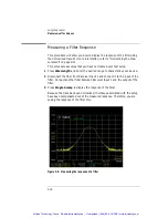
Page 137: ...racterize your device 2 Disconnect the fiber from Receiver Input 1 and connect it to the input of the filter Connect another fiber between Receiver Input 1 and the output of the filter 3 Press Single Sweep to display the response of the filter Because the trace has been normalized the losses associated with the setup have been compensated out of the measured response Therefore you are seeing the r...

Page 138: ...3 19 Using the Analyzer Measurement Techniques This page left intentionally blank Artisan Technology Group Quality Instrumentation Guaranteed 888 88 SOURCE www artisantg com ...

Page 139: ...ure assumes that you have normalized your test setup and posi tioned the response on the display For more information on these processes refer to Normalizing the Measurement on page 3 11 and refer to Status Reporting for Laser Wavelength Zeroing on page 3 13 Press Wavelength Span and reduce the span to 2 nm Reducing the span allows you to zoom in on desired portions of the response Artisan Technol...

Page 140: ...3 21 Using the Analyzer Measurement Techniques Figure 3 6 Zooming in on a portion of a response Artisan Technology Group Quality Instrumentation Guaranteed 888 88 SOURCE www artisantg com ...

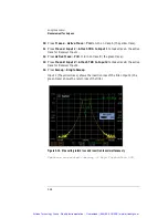
Page 141: ... Markers Peak Search to find the highest peak in the displayed response 2 Press More Marker Functions Marker BW On 3 dB to measure the 3 dB bandwidth point of the peak The measurement results are displayed at the top of the screen Mkr 1 shows the peak wavelength and amplitude Mkr 1L displays the rising edge of the 3 dB wavelength and amplitude Mkr 1R displays the falling edge of the 3 dB wavelengt...

Page 142: ...3 23 Using the Analyzer Measurement Techniques Figure 3 7 Measuring 3 dB bandwidth of a filter Artisan Technology Group Quality Instrumentation Guaranteed 888 88 SOURCE www artisantg com ...

Page 143: ... selected overlaps the normalized wave length range only the normalized portion of the trace will be displayed 3 Press Norm Ref to access the Normalization menu 4 Press Normalize Setup and make changes as applicable for your device 5 Press Close Panel and then press Normalize Input 1 The message Normalizing receiver input 1 please wait will be displayed at the bottom of the screen The normalizatio...

Page 144: ...3 25 Using the Analyzer Measurement Techniques Figure 3 8 Measuring insertion loss Artisan Technology Group Quality Instrumentation Guaranteed 888 88 SOURCE www artisantg com ...

Page 145: ...recise reference for reflection measurements Return loss is specified at 0 18 dB 0 1 dB 96 2 1 Connect the equipment as shown in Figure 3 9 Figure 3 9 Normalize Receiver Input 2 setup 2 Press Normalize Ref to access the Normalization menu 3 Press Normalize Setup and make changes as applicable for your device 4 Press Normalize Input 2 to normalize the return loss path for the device Connecting the ...

Page 146: ... Normalize Input 1 7 Connect the equipment as shown in Figure 3 11 Figure 3 11 Measuring insertion loss and return loss setup 8 Press Wavelength and set the Center WL to the wavelength of the DUT 9 Press Span and choose a narrow span For example 2 nm Artisan Technology Group Quality Instrumentation Guaranteed 888 88 SOURCE www artisantg com ...

Page 147: ... trace 13 Press Trace B Input 2 Attach TRB to Input 2 to make trace B the active trace for Receiver Input 2 14 Press Sweep Single Sweep Input 1 the yellow trace shows the insertion loss of the filter Input 2 the green trace shows the return loss of the filter Figure 3 12 Measuring return loss and insertion loss simultaneously Spectrum re printed courtesy of Hoya Corporation USA Artisan Technology ...

Page 148: ...lay makes it easy to identify the state of each marker Information provided for each marker includes Wavelength Amplitude The trace associated with the marker For example if marker 1 is on Trace A then the annotation will show Mkr1 A In addition if there are markers on two different traces then the delta of the wavelength and amplitude for the two different markers is also displayed For example Mk...

Page 149: ...s This procedure assumes that you have normalized your test setup and posi tioned the response on the display For more information on these processes refer to Normalizing the Measurement on page 3 11 and refer to Status Reporting for Laser Wavelength Zeroing on page 3 13 1 From the front panel press Markers Active Trace and select the first trace to place a marker 2 Press Active Marker Mkr 1 Peak ...

Page 150: ...31 Using the Analyzer Measurement Techniques Figure 3 13 Wavelength and amplitude difference between two signals Artisan Technology Group Quality Instrumentation Guaranteed 888 88 SOURCE www artisantg com ...

Page 151: ...e at the top of screen by going into Amplitude Amplitude Setup and setting the Reference Level Position to 10 divi sions This has the advantage that Amplitude Peak To REF LEVEL will put the top of the trace in its optimum position Like the top of screen the instrument uses the normalization data to convert sensitivity back to an absolute signal level in dBm The WDCA has a specified receiver noise ...

Page 152: ...litude and wavelength specifications than precision or normal so it can use more fil tering without slowing the sweep down In addition because it starts at the 40 nm s laser source sweep rate it can reduce the sweep rate down to 5 nm s before the Acc Unspec notation appears For very long sweeps it may not make sense to sweep twice in order to cover multiple gain ranges The WDCA allows the user to ...

Page 153: ...n Make sure that auto sensitivity is on Amplitude Sensitivity Auto 4 Place a marker on the lowest amplitude feature of the trace you would like to characterize using Markers Note the sweep to sweep variation 5 If the sweep to sweep variation is too high for your needs increase the sensitivity until the sweep to sweep variation is acceptable The sweep will slow down and multiple sweeps per trace up...

Page 154: ...35 Using the Analyzer Measurement Techniques Figure 3 14 Auto sensitivity versus manual sensitivity set to 60 dB Artisan Technology Group Quality Instrumentation Guaranteed 888 88 SOURCE www artisantg com ...

Page 155: ... pair must indicate whether the current data point will be connected to the previous data point Each data point pair must be on a separate line Limit lines are only available for relative dB mode not for absolute dBm mode Tip For your convenience instructional text denoted by number signs surrounding the text has been added to each of the supplied limit line files This will make it easy to remembe...

Page 156: ...e used to test the upper limits of the response 4 Scroll down to the current data point entries Click and drag all data entries to select then press the Delete key 5 To specify the first data point at a wavelength of 1538 nm and an amplitude of 18 8 db type 1 538e 6 18 8 1 The 1 indicates that this data point will be connected to the previous data point For the first data point only the Connect to...

Page 157: ... the PC and insert it into the disk drive of the WDCA 9 Setup the WDCA to display the response of your device Refer to Status Reporting for Laser Wavelength Zeroing on page 3 13 for more information 10 From the front panel press Amplitude Limit Lines Load Limit Lines Load Limit Line 1 11 From the Limit Line catalog select the newly created limit line and then press Load File 12 Press Previous Menu...

Page 158: ...3 39 Using the Analyzer Measurement Techniques Figure 3 16 Upper and lower limit lines showing pass fail test Artisan Technology Group Quality Instrumentation Guaranteed 888 88 SOURCE www artisantg com ...

Page 159: ...Insertion Loss and Return Loss Simultaneously on page 3 26 2 From the front panel press Traces Trace Math Default Math Trace C Log Math C A B to add the insertion loss and return loss traces and display the results in Trace C 3 If the DUT is 100 efficient then Trace C will be at 0 dB Any variation from 0 dB will show you the losses of the DUT Artisan Technology Group Quality Instrumentation Guaran...

Page 160: ...tup your device so that you can view the response on the display 2 From the front panel press Traces Active Trace TrA 3 Press Single Sweep to update Trace A then press Update A off 4 Press Active Trace TrB 5 Press Sweep Repeat Sweep On to continuously update the measured response on Trace B 6 Press Traces Trace Math Off Default Math Trace C Log Math C A B You can now monitor the wavelength drift o...

Page 161: ...3 42 Using the Analyzer Measurement Techniques Artisan Technology Group Quality Instrumentation Guaranteed 888 88 SOURCE www artisantg com ...

Page 162: ...e Network 4 6 Using the Reflection X Emulator to Run the Remote Front Panel 4 7 Using the X Win 32 Emulator to Run the Remote Front Panel 4 9 Using a UNIX Workstation to Run the Remote Front Panel 4 12 Using the Remote Front Panel 4 14 Remote Front Panel Operation Artisan Technology Group Quality Instrumentation Guaranteed 888 88 SOURCE www artisantg com ...

Page 163: ... analyzer and added to the DNS utilized by your PC or UNIX workstation Gateway and Net Mask information will also need to be specified in order for the analyzer to communicate with the LAN The new Internet Protocol IP address is used to uniquely identify the network address of the analyzer An IP address is a set of four decimal num bers separated by periods like 192 170 128 21 The Hostname associa...

Page 164: ...l use the DNS to lookup the analyzer location by the host name Any DNS local domain name and NIS information entered will not be used in configuring the ana lyzer network for Remote Front Panel operation 2 A keyboard and mouse must be attached to the analyzer to complete the procedure Restart the analyzer after connecting the keyboard and mouse 3 Before using the remote front panel the analyzer mu...

Page 165: ...config will disable the current network configuration if any 4 The HP UX Set Systems Parameters panel is displayed You will use this panel to supply the information needed to configure the analyzer on the network Press Yes to continue 5 Enter the Host Name for your analyzer then press OK 6 You will now be prompted to enter the time zone settings for the analyzer It is important that the analyzer t...

Page 166: ... for this application 14 When prompted for the NIS Domain Name and NIS Server Name press Cancel This is not required for this application 15 When prompted to Restart the analyzer press Yes Reboot The analyzer will take approximately five minutes to restart Artisan Technology Group Quality Instrumentation Guaranteed 888 88 SOURCE www artisantg com ...

Page 167: ...ront panel ensure That the analyzer is connected to the local area network LAN There are no Proxies between the analyzer and the remote system That the underlying network operates fast enough to allow for reasonable operation of the analyzer If using a PC to run the remote front panel operation an X Windowing emulator is available on the PC With the exception of the power switch and knob all front...

Page 168: ...Run the Remote Front Panel Below are the basic steps for setting up the Reflection X emulator to run the analyzer remote front panel Refer to the Reflection X documentation for fur ther information Artisan Technology Group Quality Instrumentation Guaranteed 888 88 SOURCE www artisantg com ...

Page 169: ...he Host Name field select the name assigned to the analyzer d In the User Name field enter osaadm e In the Password field enter osaosa1 f In the Command field you will need to modify the existing command as follows usr bin x11 hpterm fn 6x13 sb ls display IP name T exec etc map_display g Click Connect to start the remote front panel controller 3 Continue to Using the Remote Front Panel on page 4 1...

Page 170: ...emulator to run the ana lyzer remote front panel Refer to the X Win 32 documentation for further information 1 From the PC Start menu click X Win32 X Win Config 2 From the X Win32 Configuration window click Add 3 In the Connect Method window select rexec and then click Next Artisan Technology Group Quality Instrumentation Guaranteed 888 88 SOURCE www artisantg com ...

Page 171: ...from a list of sessions b In the Host Name field enter the host name assigned to the analyzer The host name can either be the name or IP address of the remote host you want to connect to for example analyzer analyzernet com or 247 109 121 43 c In the Login name field enter osaadm d In the Command field you will need to enter the command as follows usr dt bin hpterm display 141 121 12 345 0 0 exec ...

Page 172: ... 32 X Win 32 You will notice that an X icon will appear in your windows tray usually located in the lower right hand part of your display 6 Click on the X icon and select the desired analyzer session to run the remote front panel operation 7 Continue to Using the Remote Front Panel on page 4 14 Artisan Technology Group Quality Instrumentation Guaranteed 888 88 SOURCE www artisantg com ...

Page 173: ...eady changed it and then press Enter 5 At the prompt type etc map_display and then press Enter to start the remote front panel controller 6 A Welcome screen is displayed and you are given three command choices Display accesses a diagnostic tool to show the display parameter setup Enable accesses the remote front panel This command is used to stop the analyzer from operating in normal mode and star...

Page 174: ...r will be restarted You will be able to monitor the restarting process on the PC display Once the analyzer has finished restarting the front panel will be activated on your PC display 9 You can now use the remote front panel just like you would if you were sitting in front of the analyzer Remember to use the main menu bar to access analyzer functions and to enter data via the keyboard number keys ...

Page 175: ...enter a new password The new password must differ from the old password by at least three charac ters N o t e Once you change the password you will need to remember it for future use You will not be able to access the remote front panel capabilities without the new password 2 From the command prompt type Enable The remote front panel command will be displayed on the analyzer and the analyzer will ...

Page 176: ...CA 5 11 SCPI Syntax Rules 5 14 Monitoring the Instrument 5 20 WDCA Techniques to Improve Throughput 5 28 Example Programs 5 33 Front Panel Functions to Remote Commands 5 81 Remote Operation Artisan Technology Group Quality Instrumentation Guaranteed 888 88 SOURCE www artisantg com ...

Page 177: ...n running you will want to review Techniques to Improve Throughput on page 5 28 to improve your measurement throughput In this chapter a special font is used for GPIB commands which can be sent to the instrument Because there are so many different GPIB control platforms the in line code examples use a platform independent pseudo code sendMessage xxxxx means to send the text string xxxxx to the ins...

Page 178: ...ckard and Agilent Technologies that is portable across many sys tems and I O interfaces For more detailed information regarding GPIB the IEEE 488 2 standard or the SCPI standard refer to the following books SCPI Consortium SCPI Standard Commands for Programmable Instru ments 1999 International Institute of Electrical and Electronics Engineers IEEE Standard 488 1 1987 IEEE Standard Digital Interfac...

Page 179: ...B control Indicates that the instrument has requested service from the computer Refer to Monitoring the Instrument on page 5 20 Pressing this button activates the front panel keys after a computer has had control of the instrument Artisan Technology Group Quality Instrumentation Guaranteed 888 88 SOURCE www artisantg com ...

Page 180: ...ave length Calibration on page 3 17 for more information Lambda Zero The WDCA employs a tunable laser with mechanical components that must be periodically realigned The instrument will automatically execute the realign ment as needed This is called Lambda Zero In addition the instrument pro vides a prediction in minutes when the next re alignment will occur Once a realignment begins the WDCA will ...

Page 181: ...ing HP Basic for Windows you will need to enable EOI each time you open a session to the instrument This is done using the ASSIGN WDCA key words and associating the END key word with the session Use device clear The WDCA uses the Selected Device Clear interface message to free the instrument from error conditions Clearing the instrument at the start of any control application will avoid confusing ...

Page 182: ...The recommended technique for waiting is to use the query form of OPC OPC This way after initiating the sweep you can do other things while waiting for the instrument When you do wait make sure your GPIB time out is longer than what the instrument needs to finish the command A typical sequence would be sendMessage INIT OPC take a sweep perform other tasks while waiting receiveInteger wait for 1 in...

Page 183: ...ent display and is added to the error queue Whenever there are messages in the error queue bit 2 of the status byte is set The recommended practice is to use serial poll to read the status byte and then use a bitwise and against the value 4 to see if the bit is set If it is set you should use SYSTem ERRor to read all the error messages until you get a response that begins with 0 indicating no furt...

Page 184: ... DC RANGE LOWer Sets the sensitivity The sensitivity is the smallest amplitude to be measured relative to the top grati cule of the display DISP TRAC Y RLEV 10 dBm DISPlay WINDow 1 TRACe Y 1 2 SCALe RLEVel Set the display reference level the maximum power expected to display INIT INITiate IMMediate Take a sweep INIT NORM INITiate NORMalize Performs a system normalization Insure that a patch cord i...

Page 185: ...e MARKer 1 2 3 4 MAXimum Positions marker 1 to the maximum amplitude point CALC MARK1 X CALCulate MARKer 1 2 3 4 X Read back marker 1 wavelength CALC MARK1 Y CALCulate MARKer 1 2 3 4 Y Read back marker 1 amplitude TRAC TRA TRACe DATA Y TRA TRB TRC TRD TRE TRF Transfer entire trace according to format set with the FORM command IDN Return string describing model number serial number and software ver...

Page 186: ...er the instrument is in Remote mode the RMT message is displayed on the instrument s screen and all keys are disabled except for the front panel LOCAL key This key can be pressed by the user to restore front panel control of the instrument even when the display is off You can specify a local lockout mode that deactivates the front panel LOCAL key If the instrument is in local lockout mode all the ...

Page 187: ...r1 MAXimum CALCulate MARKer1 X value readDoubleReply inst where sendCommand is a routine in your favorite language using your favorite inter face to send a command to the WDCA inst is a handle to the WDCA appropriate to the interface you are using readIntReply is a routine in your favorite language using your favorite interface to read a reply from the WDCA and convert it to an integer readDoubleR...

Page 188: ... condition sendCommand inst ESR value readIntReply inst end if where serialPoll is a routine written in your favorite language using your favorite in terface to perform a serial poll WAI Command The other synchronization command provided is WAI This command is iden tical to OPC but there is no external indication that the command is complete It forces the instrument to finish the commands received...

Page 189: ...nt and received only as ASCII strings with the exception of the following commands These commands can send and receive floating point binary data in IEEE 488 2 indefinite or definite length blocks HCOPy DATA MMEMory DATA TRACe DATA Y POWER TRACe DATA Y RATio TRACe DATA Y MEMory STATe EXTended Artisan Technology Group Quality Instrumentation Guaranteed 888 88 SOURCE www artisantg com ...

Page 190: ...to standard MS DOS a file naming conventions a MS DOS is a U S registered trademark of Microsoft Corporation trace_name TRA TRB TRC TRD TRE TRF data_block This parameter represents the arbitrary block program data as defined by IEEE 488 2 Arbitrary block program data allows any 8 bit bytes to be transmitted This includes extended ASCII control codes and symbols Two types of data blocks are defined...

Page 191: ... for creating short forms from the long form are as follows The mnemonic is the first four characters of the keyword unless the fourth character is a vowel in which case the mnemonic is the first three char acters of the keyword This rule is not used if the length of the keyword is exactly four characters You can use upper or lowercase letters Program headers can be sent using any combination of u...

Page 192: ...d from another subsystem sendMessage SENSe WAVelength SPAN FULL CALCulate MARKer1 MAXimum Sending common commands If a subsystem has been selected and a common command is received by the instrument the instrument remains in the selected subsystem For example if the command sendMessage SENSe WAVelength STARt 1550NM CLS STOP 1550NM is sent to the instrument the Sense subsystem remains selected If so...

Page 193: ... table below lists the available multipliers If a measurement cannot be made no numerical response is given and an error is placed into the error queue For example RST CALCulate1 MARKer1 X will timeout the controller and place a Settings conflict error in the error queue because no marker has been enabled Program message terminator The string of instructions sent to the instrument is executed afte...

Page 194: ...uage interface to read the response passes the value across the bus to the controller Sending another command or query before reading the result of a query causes the output queue to be cleared and the current response to be lost This generates an error in the error queue The output of the instrument may be numeric or character data depending on what is que ried Refer to the specific commands for ...

Page 195: ...s that you can use to enable or disable the reporting of individual bits from an event register For example you can disable the reporting of the Sweeping bit in the Operation Status structure so that even though it goes high in the registers it can never set the summary bit 7 in the Status Byte high Querying a register always returns the value as a decimal weighted sum of all set bits Refer to Tab...

Page 196: ...ry bits that monitor activity in the other sta tus registers and queues The register s bits are set and cleared by summary bits from other registers or queues If a bit in the Status Byte goes high query the value of the source register to determine the cause Command Use GPIB serial poll command Returns the status byte value Reads bit 6 as the Request Service RQS bit and clears the bit which clears...

Page 197: ...Structure Contains bits that report on the instrument s normal operation Additional transition filters give you the ability to select the logic transitions which set the event register bits For example you can define the Measuring bit of the Operation Status Structure to be set when a status line transitions from false to true This is a positive transition You can also specify a negative transitio...

Page 198: ...ands and queries that you send to the instrument The output queue generates the Message Available Summary bit when the output queue contains one or more bytes This summary bit sets the MAV bit bit 4 in the Status Byte The method used to read the output queue depends upon the programming language and environment For example with HP BASIC the output queue may be read using the ENTER statement Table ...

Page 199: ...flows the least recent errors remain in the queue and the most recent error is discarded The length of the instrument s error queue is 30 29 positions for the error messages and 1 position for the Queue overflow message Querying errors removes the oldest error from the head of the queue which opens a position at the tail of the queue for a new error When all the errors have been read from the queu...

Page 200: ...malized data will be valid only for normal sweep mode It is recommended that you perform a normalization every 8 hours Tip The normalized wavelength range is independent of the displayed mea surement wavelength range This allows you to calibrate a wider wavelength range and then perform a measurement on a subset of the normalized range However if the wavelength range selected extends outside the n...

Page 201: ...SENSe NORMalize WAVelength STOP wavelength To perform a normalization connect a short cable from the laser to receiver input l SENSe NORMalize WAVelength STARt 1540 nm SENSe NORMalize WAVelength STOP 1543 nm INITiate NORMalize 1 To turn normalization on SENSe NORMalize ENABle 1 ON To read settings back SENSe NORMalize WAVelength STARt SENSe NORMalize WAVelength STOP TRACe POINts NORM 1 To read dat...

Page 202: ... in data acquired by the WDCA You can send back in trace data taken with normalization off and send back normalization data read out of the instrument at a previous time The data must be acquired with 5 pm wavelength step Artisan Technology Group Quality Instrumentation Guaranteed 888 88 SOURCE www artisantg com ...

Page 203: ...em overhead associated with maintaining a real time display This makes software intensive operations much faster but sweep associated operations won t change very much As a result the speed improvement you will see depends on your application With the display off you can expect a typical application that is taking sweeps using markers and transferring traces to run about twice as fast To turn the ...

Page 204: ...include that in the message also Avoid putting too much in a single message as this makes it dif ficult to read and rearrange your application program contents Transfer traces when more than 2 marker operations Modern controllers have plenty of processing power to calculate trace statis tics and can often calculate faster than the instrument The rule of thumb is that if you perform more than two m...

Page 205: ...jects using Visual Basic and C With short binary transfer times the data transfer process is faster than the hardware This makes it possible to devise ways to process the data faster to keep up with the hardware Note that in Visual C it is possible to download and convert the trace in one step by changing the format string The following table and chart compare the different times it takes to trans...

Page 206: ...sion ACSII Total Binary Advantage 1000 47 78 125 219 16 235 110 2000 79 171 250 422 16 438 188 3000 110 250 360 640 31 671 311 4000 140 344 484 844 31 875 391 5000 172 437 609 1063 31 1094 485 6000 203 515 718 1282 31 1313 595 7000 234 594 828 1484 47 1531 703 8000 266 687 953 1703 63 1766 813 9000 297 781 1078 1906 63 1969 891 Artisan Technology Group Quality Instrumentation Guaranteed 888 88 SOU...

Page 207: ... traceBytes cnt 1 traceBytes cnt 2 traceBytes cnt 2 tempByte Optimize Sensitivity Sweep Mode and Wavelength Span Sensitivity is the smallest detectable signal relative to the top of the display As sensitivity increases so does the sweep time Therefore use the minimum sensitivity that allows you to discern the signals in your measurement Using auto sensitivity optimizes the sensitivity setting allo...

Page 208: ...measurements are performed and how to return data to the computer The program examples are written in Visual Basic and VC for Windows The following example programs are provided in this section Example 1 Acquire Trace 5 34 Example 2 User Calibration 5 39 Example 3 Normalization 5 42 Example 4 Markers 5 48 Example 5 Zero Span 5 55 Example 6 Acquire Binary Trace 5 61 Example 7 VC Example 5 75 Exampl...

Page 209: ...ack data Dim STB As Integer Status byte Dim Status As Long Status 0 Dim ErrMsg As String ErrMsg On Error GoTo ErrorHandler MousePointer vbHourglass Create a VISA session Status viOpenDefaultRM DefRM If Status 0 Then GoTo ErrorHandler Open a session to the WDCA Status viOpen DefRM GPIB txtGPIB_IN Text txtGPIB_PA Text 0 0 DevSessionNum If Status 0 Then GoTo ErrorHandler Clear the instrument Status v...

Page 210: ...ssionNum SENS SWE POIN 1001 Chr 10 0 If Status 0 Then GoTo ErrorHandler Set Span Status viVPrintf DevSessionNum SENS WAV SPAN Val txtSpan Text nm Chr 10 0 If Status 0 Then GoTo ErrorHandler Set sensitivity If chkSensitivityLock Value 0 Then Unlock Sensitivity Status viVPrintf DevSessionNum SENS POW DC RANG LOW AUTO OFF Chr 10 0 If Status 0 Then GoTo ErrorHandler Set Sensitivity Status viVPrintf De...

Page 211: ...e operation is complete Status viReadSTB DevSessionNum STB If Status 0 Then GoTo ErrorHandler Check bit 7 to see if a lambda zero is taking place If STB And 128 128 Then If an OPC_TMO 5 minutes goes by throw a timeout If Now 86400 TimeStart OPC_TMO 300 Then GoTo OPCTimeOut Else If a minute goes by throw a timeout If Now 86400 TimeStart OPC_TMO Then GoTo OPCTimeOut End If Loop While STB And 32 32 C...

Page 212: ...curely fastened _ vbOKOnly Timeout GoTo EndSession ErrorHandler If Err Number 0 Then If Status 0 Then VISA error MousePointer vbDefault Translate error number into a message Call viStatusDesc DevSessionNum Status ReadBuffer Trim off nulls ErrMsg TrimVISAStr ReadBuffer Post message and reset vars Call MsgBox Status vbCrLf ErrMsg vbOKOnly Error Status 0 Else Non VISA error from another function usin...

Page 213: ...g Dim Pos As Long On Error GoTo ErrorHandler Pos InStr VISAStr Chr 0 1 If Pos 1 Then TrimVISAStr Left VISAStr Pos Else TrimVISAStr Trim VISAStr End If Exit Function ErrorHandler TrimVISAStr VISAStr End Function Artisan Technology Group Quality Instrumentation Guaranteed 888 88 SOURCE www artisantg com ...

Page 214: ...Status byte Dim Status As Long Status 0 Dim ErrMsg As String ErrMsg On Error GoTo ErrorHandler Call MsgBox Connect Output 2 of the TLS to the Source Input vbOKOnly MousePointer vbHourglass Create a VISA session Status viOpenDefaultRM DefRM If Status 0 Then GoTo ErrorHandler Open a session to the WDCA Status viOpen DefRM GPIB txtGPIB_IN Text txtGPIB_PA Text 0 0 DevSessionNum If Status 0 Then GoTo E...

Page 215: ...6400 TimeStart OPC_TMO Then GoTo OPCTimeOut Check bit 5 of the status byte register to see if the operation is complete Status viReadSTB DevSessionNum STB If Status 0 Then GoTo ErrorHandler Call Sleep 5 Delay so the instrument isn t tied up with responding to STB DoEvents Loop While STB And 32 32 Clear status information Status viVPrintf DevSessionNum CLS Chr 10 0 If Status 0 Then GoTo ErrorHandle...

Page 216: ... ErrMsg vbOKOnly Error Status 0 ErrMsg Else Call MsgBox Err Number vbCrLf Err Description vbOKOnly Error End If GoTo EndSession End Sub Private Function TrimVISAStr ByVal VISAStr As String As String Dim Pos As Long On Error GoTo ErrorHandler Pos InStr VISAStr Chr 0 1 If Pos 1 Then TrimVISAStr Left VISAStr Pos Else TrimVISAStr Trim VISAStr End If Exit Function ErrorHandler TrimVISAStr VISAStr End F...

Page 217: ...oper connection If MsgBox Connect Output 1 to Input cmbInput Text vbCrLf Press OK to continue _ vbOKCancel Make connection vbCancel Then Exit Sub MousePointer vbHourglass Call function to initialize a VISA session to the WDCA Status InitVISASession txtGPIB_IN Text txtGPIB_PA Text DefRM DevSessionNum ErrMsg If Status 0 Or ErrMsg Then GoTo ErrorHandler Wavelength Start Status viVPrintf DevSessionNum...

Page 218: ... Call Sleep 10 Delay so the instrument isn t tied up with responding to STB DoEvents Loop While STB And 32 32 Clear status information Status viVPrintf DevSessionNum CLS Chr 10 0 If Status 0 Then GoTo ErrorHandler Enable normalization for the selected input Status viVPrintf DevSessionNum SENS NORM ENABLE cmbInput Text ON Chr 10 0 If Status 0 Then GoTo ErrorHandler Take a sweep and send OPC Status ...

Page 219: ... session to the WDCA Call viClose DevSessionNum End VISA session Call viClose DefRM MousePointer vbDefault Exit Sub OPCTimeOut MousePointer vbDefault Call MsgBox Timeout while waiting for OPC Make sure all cables are securely fastened _ vbOKOnly Timeout GoTo EndSession ErrorHandler If Err Number 0 Then If Status 0 Then VISA error MousePointer vbDefault Translate error number into a message Call vi...

Page 220: ... to the status byte register bit 7 decimal 128 Status viVPrintf DevSessionNum STAT OPER ENAB 4 Chr 10 0 If Status 0 Then GoTo ErrorHandler Summarize Lambda Zero Complete to the status byte register bit 3 decimal 8 Status viVPrintf DevSessionNum STAT QUES ENAB 8 Chr 10 0 If Status 0 Then GoTo ErrorHandler Check to see if a Lambda Zero is pending Status viReadSTB DevSessionNum STB If Status 0 Then G...

Page 221: ...ro Status viVPrintf DevSessionNum STAT OPER ENAB 8 Chr 10 0 If Status 0 Then GoTo ErrorHandler ErrMsg CheckLambdaZero 0 Exit Function LZ_Timeout ErrMsg Timeout while waiting for Lambda Zero to complete Make sure Output 2 is connected _ to Source Input CheckLambdaZero 0 Exit Function ErrorHandler If Err Number 0 Then CheckLambdaZero Status Else ErrMsg Err Number vbCrLf Err Description CheckLambdaZe...

Page 222: ...5 47 Remote Operation Example Programs ErrorHandler TrimVISAStr VISAStr End Function Artisan Technology Group Quality Instrumentation Guaranteed 888 88 SOURCE www artisantg com ...

Page 223: ... GoTo ErrorHandler MousePointer vbHourglass Call function to initialize a VISA session to the WDCA Status InitVISASession txtGPIB_IN Text txtGPIB_PA Text DefRM DevSessionNum ErrMsg If Status 0 Or ErrMsg Then GoTo ErrorHandler Set Center Wavelength Status viVPrintf DevSessionNum SENS WAV CENT Val txtCWL Text nm Chr 10 0 If Status 0 Then GoTo ErrorHandler Set Span Status viVPrintf DevSessionNum SENS...

Page 224: ...orHandler Take a sweep and send OPC Status viVPrintf DevSessionNum INIT IMM OPC Chr 10 0 If Status 0 Then GoTo ErrorHandler Wait for completion TimeStart Now 86400 Used to track elapsed time Do If a minute goes by throw a timeout If Now 86400 TimeStart OPC_TMO Then GoTo OPCTimeOut Check bit 5 of the status byte register to see if the operation is complete Status viReadSTB DevSessionNum STB If Stat...

Page 225: ...rMsg If Status 0 Then GoTo ErrorHandler Status viVScanf DevSessionNum t ReadBuffer If Status 0 Then GoTo ErrorHandler Call MsgBox Bandwidth TrimVISAStr ReadBuffer vbOKOnly Done EndSession On Error Resume Next Close VISA session to the WDCA Call viClose DevSessionNum End VISA session Call viClose DefRM MousePointer vbDefault Exit Sub OPCTimeOut MousePointer vbDefault Call MsgBox Timeout while waiti...

Page 226: ...n Error GoTo ErrorHandler Summarize Lambda Zero Pending to the status byte register bit 7 decimal 128 Status viVPrintf DevSessionNum STAT OPER ENAB 4 Chr 10 0 If Status 0 Then GoTo ErrorHandler Summarize Lambda Zero Complete to the status byte register bit 3 decimal 8 Status viVPrintf DevSessionNum STAT QUES ENAB 8 Chr 10 0 If Status 0 Then GoTo ErrorHandler Check to see if a Lambda Zero is pendin...

Page 227: ... DevSessionNum STAT OPER ENAB 8 Chr 10 0 If Status 0 Then GoTo ErrorHandler ErrMsg CheckLambdaZero 0 Exit Function LZ_Timeout ErrMsg Timeout while waiting for Lambda Zero to complete Make sure Output 2 is connected _ to Source Input CheckLambdaZero 0 Exit Function ErrorHandler If Err Number 0 Then CheckLambdaZero Status Else ErrMsg Err Number vbCrLf Err Description CheckLambdaZero 0 End If End Fun...

Page 228: ...rintf DevSessionNum INIT CONT 0 Chr 10 0 If Status 0 Then GoTo ErrorHandler Clear status registers Status viVPrintf DevSessionNum CLS Chr 10 0 If Status 0 Then GoTo ErrorHandler Map OPC to bit 5 of the Standard Event Status Enable Register Status viVPrintf DevSessionNum ESE 1 Chr 10 0 If Status 0 Then GoTo ErrorHandler Check for Lambda Zero Status CheckLambdaZero DevSessionNum ErrMsg If Status 0 T...

Page 229: ... String Dim Pos As Long On Error GoTo ErrorHandler Pos InStr VISAStr Chr 0 1 If Pos 1 Then TrimVISAStr Left VISAStr Pos Else TrimVISAStr Trim VISAStr End If Exit Function ErrorHandler TrimVISAStr VISAStr End Function Artisan Technology Group Quality Instrumentation Guaranteed 888 88 SOURCE www artisantg com ...

Page 230: ...rHandler MousePointer vbHourglass Call function to initialize a VISA session to the WDCA Status InitVISASession txtGPIB_IN Text txtGPIB_PA Text DefRM DevSessionNum ErrMsg If Status 0 Or ErrMsg Then GoTo ErrorHandler Set Center Wavelength Status viVPrintf DevSessionNum SENS WAV CENT Val txtCWL Text nm Chr 10 0 If Status 0 Then GoTo ErrorHandler Set sensitivity If chkSensitivityLock Value 0 Then Unl...

Page 231: ... to track elapsed time Do If a minute goes by throw a timeout If Now 86400 TimeStart OPC_TMO Then GoTo OPCTimeOut Check bit 5 of the status byte register to see if the operation is complete Status viReadSTB DevSessionNum STB If Status 0 Then GoTo ErrorHandler Call Sleep 5 Delay so the instrument isn t tied up with responding to STB DoEvents Loop While STB And 32 32 Clear status information Status ...

Page 232: ...m another function using VISA Call MsgBox ErrMsg vbOKOnly Error End If ErrMsg Else Call MsgBox Err Number vbCrLf Err Description vbOKOnly Error End If GoTo EndSession End Sub Private Function CheckLambdaZero DevSessionNum As Long Optional ErrMsg As String _ As Long This function will check to see if a TLS LambdaZero is about to occur If so force it to happen to prevent timeouts and ensure data int...

Page 233: ...ambda Zero is complete Status viReadSTB DevSessionNum STB If Status 0 Then GoTo ErrorHandler Check for timeout this could take over 5 minutes If Now 86400 TimeStart LZ_TMO Then GoTo ErrorHandler Loop While STB And 8 8 End If Clear the Status Byte Status viVPrintf DevSessionNum CLS Chr 10 0 If Status 0 Then GoTo ErrorHandler Summarize Lambda Zero In Progress to the status byte bit 7 decimal 128 Thi...

Page 234: ...If Status 0 Then GoTo ErrorHandler Set write buffer to flush on access Status viSetAttribute DevSessionNum VI_ATTR_WR_BUF_OPER_MODE VI_FLUSH_ON_ACCESS If Status 0 Then GoTo ErrorHandler Set read buffer to flush on access Status viSetAttribute DevSessionNum VI_ATTR_RD_BUF_OPER_MODE VI_FLUSH_ON_ACCESS If Status 0 Then GoTo ErrorHandler Ensure that the instrument isn t in repeat sweep mode Status viV...

Page 235: ...fer Trim off nulls ErrMsg TrimVISAStr ReadBuffer InitVISASession Status Else ErrMsg Err Number vbCrLf Err Description End If End Function Private Function TrimVISAStr ByVal VISAStr As String As String Dim Pos As Long On Error GoTo ErrorHandler Pos InStr VISAStr Chr 0 1 If Pos 1 Then TrimVISAStr Left VISAStr Pos Else TrimVISAStr Trim VISAStr End If Exit Function ErrorHandler TrimVISAStr VISAStr End...

Page 236: ...ring 65500 Dim AscBuffer As String Fixed length strings may not be large enough for ASCII downloads Dim STB As Integer Status byte Dim Status As Long Status 0 Dim ErrMsg As String ErrMsg Performance timers for Binary Trace Dim oBinTraceBench As clsStopWatch Dim oBinCnvrtBench As clsStopWatch Dim dBinTraceBench As Double Dim dBinCnvrtBench As Double Performance timers for ASCII Trace Dim oAscTraceB...

Page 237: ...tatus viVPrintf DevSessionNum SENS POW DC RANG LOW AUTO OFF Chr 10 0 If Status 0 Then GoTo ErrorHandler Set Sensitivity Status viVPrintf DevSessionNum SENS POW DC RANG LOW Val txtSensitivity Text _ Chr 10 0 If Status 0 Then GoTo ErrorHandler Else Lock Sensitivity Status viVPrintf DevSessionNum SENS POW DC RANG LOW AUTO ON Chr 10 0 If Status 0 Then GoTo ErrorHandler End If Sweep Mode Status viVPrin...

Page 238: ...o ErrorHandler Download results as Binary Format data as REAL32 Status viVPrintf DevSessionNum FORM DATA REAL 32 Chr 10 0 If Status 0 Then GoTo ErrorHandler Time the data transfer Call oBinTraceBench StopWatch swStart Send query to acquire Trace Status viVPrintf DevSessionNum TRAC cmbTrace Text Chr 10 0 If Status 0 Then GoTo ErrorHandler Read the trace from the buffer Status viVScanf DevSessionNum...

Page 239: ...POIN Chr 10 0 If Status 0 Then GoTo ErrorHandler Read the number of trace points from the buffer Status viVScanf DevSessionNum t ReadBuffer If Status 0 Then GoTo ErrorHandler Shave off end nulls and convert to integer numPoints CInt TrimVISAStr ReadBuffer Parse comma delimited array string Status modConvert ASCToArray AscBuffer numPoints dAscTrace ErrMsg If Status 0 Then Call Err Raise Status ASCT...

Page 240: ...sion ErrorHandler If Err Number 0 Then If Status 0 Then VISA error MousePointer vbDefault Translate error number into a message Call viStatusDesc DevSessionNum Status ReadBuffer Trim off nulls ErrMsg TrimVISAStr ReadBuffer Post message and reset vars Call MsgBox Status vbCrLf ErrMsg vbOKOnly Error Status 0 Else Non VISA error from another function using VISA Call MsgBox ErrMsg vbOKOnly Error End I...

Page 241: ...us viReadSTB DevSessionNum STB If Status 0 Then GoTo ErrorHandler If a Lambda Zero is pending force it to occur If STB And 128 128 Then Start Lambda Zero Status viVPrintf DevSessionNum CAL WAV INT Chr 10 0 If Status 0 Then GoTo ErrorHandler TimeStart Now 86400 Used to track elapsed time Wait for Lambda Zero to complete Do Call Sleep 5 DoEvents Read STB to determine when Lambda Zero is complete Sta...

Page 242: ...ReadBuffer As String 65500 Buffer to read back data Dim Status As Long Status 0 On Error GoTo ErrorHandler Create a VISA session Status viOpenDefaultRM DefRM If Status 0 Then GoTo ErrorHandler Open a session to the WDCA Status viOpen DefRM GPIB GPIB_IN GPIB_PA 0 0 DevSessionNum If Status 0 Then GoTo ErrorHandler Clear the instrument Status viClear DevSessionNum If Status 0 Then GoTo ErrorHandler S...

Page 243: ... DevSessionNum FORM DATA ASCII Chr 10 0 If Status 0 Then GoTo ErrorHandler Status 0 ErrMsg Exit Function ErrorHandler If Err Number 0 Then Translate error number into a message Call viStatusDesc DevSessionNum Status ReadBuffer Trim off nulls ErrMsg TrimVISAStr ReadBuffer InitVISASession Status Else ErrMsg Err Number vbCrLf Err Description End If End Function Private Function TrimVISAStr ByVal VISA...

Page 244: ...a InStr PrvComma 1 ASCTrace The last value wont have a comma If NxtComma 0 Then NxtComma Len ASCTrace Next i End If ErrMsg ASCToArray 0 Exit Function ErrorHandler ErrMsg Err Description ASCToArray Err Number End Function Public Function BinASCToArray ByVal BinASCTrace As String ByVal eDataSize As enumDataSize _ ByRef dResult As Double Optional ErrMsg As String As Long The REAL format is a definite...

Page 245: ... more for first value StartPos 3 NumLengthBytes Resize result array according to the number of points ReDim dResult 0 To numPoints 1 As Double For i 0 To numPoints 1 Pull out the next value in the trace ValStr Mid BinASCTrace i NumBytes StartPos NumBytes Convert the binary value to a double and store it in the array dResult i prvtBinASCToDouble ValStr eDataSize Status ErrMsg If Status 0 Then Call ...

Page 246: ...1 End If The binary string contains ASCII character codes Convert this to true binary BinaryStr prvtBinASCToBinStr BinASCVal Check sign bit If Left BinaryStr 1 1 Then SignBit 1 Translate exponent to decimal number Exp prvtBinStrToDec Mid BinaryStr EXP_START ExpSize Status ErrMsg If Status 0 Then Call Err Raise Status prvtBinStrToDec ErrMsg If Exp is not 0 the value is normalized If Exp 0 Then Furt...

Page 247: ...ld return an error Check status number If Status 0 Then Call Err Raise Status prvtBinStrToDec ErrMsg Else Mantissa is 0 If exponent portion of binary string is 0 then the value is 0 If prvtBinStrToDec Mid BinaryStr EXP_START ExpSize Status ErrMsg 0 Then Mantissa 0 Exp 0 SignBit 0 End If End If prvtBinASCToDouble SignBit Mantissa Exp ErrMsg ErrNum 0 Exit Function ErrorHandler ErrMsg Err Description...

Page 248: ...Bin 0000 Case 1 NewBin 0001 Case 2 NewBin 0010 Case 3 NewBin 0011 Case 4 NewBin 0100 Case 5 NewBin 0101 Case 6 NewBin 0110 Case 7 NewBin 0111 Case 8 NewBin 1000 Case 9 NewBin 1001 Case A NewBin 1010 Case B NewBin 1011 Case C NewBin 1100 Case D NewBin 1101 Case E NewBin 1110 Case F NewBin 1111 End Select TempBin TempBin NewBin Next j Next i prvtBinASCToBinStr TempBin Artisan Technology Group Qualit...

Page 249: ...nteger Dim MaxLen As Integer On Error GoTo ErrorHandler Find every 1 and calculate its value MaxLen Len BinASC NextOne InStr BinASC 1 Make sure 0 wasn t passed in If NextOne 0 Then Do Add up all the 1s 2 n TempVal TempVal 2 MaxLen NextOne Find the next 1 NextOne InStr NextOne 1 BinASC 1 Loop While NextOne 0 0 is returned when there are no more matches End If prvtBinStrToDec TempVal ErrMsg ErrNum 0...

Page 250: ...anager ViSession Inst Instrument session ViStatus status 0 ViUInt16 STB 0 VISA Return vars float fData 9601 9601 is the maximum number of points short int NumPoints 9601 unsigned char PointsStr 5 Timer Vars all values are in ms long StartTime long EndTime long ElapsedTime Open a session to the VISA Resource Manager status viOpenDefaultRM DefRM Add code to check status for an error Open a session t...

Page 251: ... viPrintf Inst SENS SWE POIN TRA n Add code to check status for an error Read back the number of points status viScanf Inst t PointsStr Add code to check status for an error Download the trace Send query to download the trace status viPrintf Inst TRAC TRA n Add code to check status for an error Read trace from buffer status viScanf Inst 9601zb fData Add code to check status for an error Calculate ...

Page 252: ...ler MousePointer vbHourglass Call function to initialize a VISA session to the WDCA Status InitVISASession txtGPIB_IN Text txtGPIB_PA Text DefRM DevSessionNum ErrMsg If Status 0 Or ErrMsg Then GoTo ErrorHandler Preset the instrument and send OPC Status viVPrintf DevSessionNum RST OPC Chr 10 0 If Status 0 Then GoTo ErrorHandler Wait for completion TimeStart Now 86400 Used to track elapsed time Do I...

Page 253: ...out GoTo EndSession ErrorHandler If Err Number 0 Then If Status 0 Then VISA error MousePointer vbDefault Translate error number into a message Call viStatusDesc DevSessionNum Status ReadBuffer Trim off nulls ErrMsg TrimVISAStr ReadBuffer Post message and reset vars Call MsgBox Status vbCrLf ErrMsg vbOKOnly Error Status 0 Else Non VISA error from another function using VISA Call MsgBox ErrMsg vbOKO...

Page 254: ...f Status 0 Then GoTo ErrorHandler Set read buffer to flush on access Status viSetAttribute DevSessionNum VI_ATTR_RD_BUF_OPER_MODE VI_FLUSH_ON_ACCESS If Status 0 Then GoTo ErrorHandler Ensure that the instrument isn t in repeat sweep mode Status viVPrintf DevSessionNum INIT CONT 0 Chr 10 0 If Status 0 Then GoTo ErrorHandler Clear status registers Status viVPrintf DevSessionNum CLS Chr 10 0 If Statu...

Page 255: ...Number vbCrLf Err Description End If End Function Private Function TrimVISAStr ByVal VISAStr As String As String Dim Pos As Long On Error GoTo ErrorHandler Pos InStr VISAStr Chr 0 1 If Pos 1 Then TrimVISAStr Left VISAStr Pos Else TrimVISAStr Trim VISAStr End If Exit Function ErrorHandler TrimVISAStr VISAStr End Function Artisan Technology Group Quality Instrumentation Guaranteed 888 88 SOURCE www ...

Page 256: ...vel Limit Lines Load Limit Lines MMEMory LOAD LLINE 1 2 file_name INTernal FLOPpy Limit Line Tests 1 2 Both Off CALCulate 1 2 3 4 5 6 LLINe 1 2 Norm Ref Normalize Setup Start Wavelength SENSe NORMalize WAVelength STARt Stop Wavelength SENSe NORMalize WAVelength STOP Normalize Input 1 INITiate NORMalize Normalize Input 2 INITiate NORMalize Apply Input 1 Normalization SENSe NORMalize ENABle Apply In...

Page 257: ... Search Menu Search Mode Peak Peak Search CALCulate 1 2 3 4 5 6 MARKer 1 2 3 4 MAXimum Next Peak Down CALCulate 1 2 3 4 5 6 MARKer 1 2 3 4 MAXimum NEXT Next Peak Left CALCulate 1 2 3 4 5 6 MARKer 1 2 3 4 MAXimum LEFT Next Peak Right CALCulate 1 2 3 4 5 6 MARKer 1 2 3 4 MAXimum RIGHt Active Marker 1 2 3 4 Off CALCulate 1 2 3 4 5 6 MARKer 1 2 3 4 STATe CALCulate 1 2 3 4 5 6 MARKer 1 2 3 4 AOFF Searc...

Page 258: ...kers Off CALCulate 1 2 3 4 5 6 MARKer 1 2 3 4 SRANge OFF Normalization Ref Normalize Setup Start Wavelength SENSe NORMalize WAVelength STARt Stop Wavelength SENSe NORMalize WAVelength STOP Normalize Input 1 INITiate NORMalize Normalize Input 2 INITiate NORMalize Apply Input 1 Normalization SENSe NORMalize ENABle Apply Input 2 Normalization SENSe NORMalize ENABle Preset SYSTem PRESet Print HCOPy IM...

Page 259: ...TEXT DATA Laser State On Off OUTPut STATe Printer Setup Printer Location HCOPy DESTination Wavelength Calibration Perform Calibration CALibration WAVelength INTernal Move Active Area More System Functions State Info Display Setup Set Time Date Remote Setup Service Menu Factory Preset Configure Network Firmware Upgrade Adv Service Functions Zero Now CALibration ZERO AUTO ONCE More Adv Service Menu ...

Page 260: ...n Math C A B CALCulate3 MATH EXPRession TRA TRB Log Math C A B CALCulate3 MATH EXPRession TRA TRB Log Math C A B CALCulate3 MATH EXPRession TRA TRB Trace C Math Off CALCulate3 MATH STATE Trace F Math Off CALCulate6 MATH STATE Trace Offset CALCulate 1 2 3 4 5 6 OFFset Exchange Math TRACe EXCHange Wavelength Center Wavelength SENSe WAVelength CENTer Span SENSe WAVelength SPAN Start Wavelength SENSe ...

Page 261: ...avelength Step Size SENse WAVelength CENTer STEP INCRement Table 5 10 Front Panel Function to Remote Command for the Agilent86082A 6 of 6 Front Panel Function Remote Command Artisan Technology Group Quality Instrumentation Guaranteed 888 88 SOURCE www artisantg com ...

Page 262: ... 74 INITiate Subsystem Commands 6 76 MEMory Subsystem Commands 6 78 MMEMory Subsystem Commands 6 79 OUTPut Subsystem Commands 6 82 SENSe Subsystem Commands 6 83 STATus Subsystem Commands 6 91 SYSTem Subsystem Commands 6 96 TRACe Subsystem Commands 6 101 UNIT Subsystem Commands 6 107 Agilent 86140B Series Command Compatibility to Agilent 86082A Series 6 109 Programming Commands Artisan Technology G...

Page 263: ... 2 the instrument s commands are grouped into subsystems Commands in each subsystem perform similar tasks The following sub systems are provided Common commands CALCulate CALibration DISPlay FORMat HCOPy INITiate MEMory MMEMory OUTPut SENSe STATus SYSTem TRACe UNIT Artisan Technology Group Quality Instrumentation Guaranteed 888 88 SOURCE www artisantg com ...

Page 264: ...ariable for which you provide a descriptive name Any letter Aa Zz followed by letters digits 0 9 and underscore _ Only the first 32 characters are significant spec_min infinity The parameter VSHFBPLQ cannot be a variable only a constant or DEFAULT spec_max infinity The parameter VSHFBPD cannot be a variable only a constant or DEFAULT from Start wavelength or frequency of trace in nm default or THz...

Page 265: ...3 4 5 6 MARKer 1 2 3 4 SRLevel Limit Lines Load Limit Lines MMEMory LOAD LLINE 1 2 file_name INTernal FLOPpy Limit Line Tests 1 2 Both Off CALCulate 1 2 3 4 5 6 LLINe 1 2 DISPlay Norm Ref Normalize Setup Start Wavelength SENSe NORMalize WAVelength STARt Stop Wavelength SENSe NORMalize WAVelength STOP Normalize Input 1 INITiate NORMalize Normalize Input 2 INITiate NORMalize Apply Input 1 Normalizat...

Page 266: ...Menu Search Mode Peak Peak Search CALCulate 1 2 3 4 5 6 MARKer 1 2 3 4 MAXimum Next Peak Down CALCulate 1 2 3 4 5 6 MARKer 1 2 3 4 MAXimum NEXT Next Peak Left CALCulate 1 2 3 4 5 6 MARKer 1 2 3 4 MAXimum LEFT Next Peak Right CALCulate 1 2 3 4 5 6 MARKer 1 2 3 4 MAXimum RIGHt Active Marker 1 2 3 4 Off CALCulate 1 2 3 4 5 6 MARKer 1 2 3 4 STATe CALCulate 1 2 3 4 5 6 MARKer 1 2 3 4 AOFF Search Mode P...

Page 267: ...s Off CALCulate 1 2 3 4 5 6 MARKer 1 2 3 4 SRANge OFF Normalization Ref Normalize Setup Start Wavelength SENSe NORMalize WAVelength STARt Stop Wavelength SENSe NORMalize WAVelength STOP Normalize Input 1 INITiate NORMalize Normalize Input 2 INITiate NORMalize Apply Input 1 Normalization SENSe NORMalize ENABle Apply Input 2 Normalization SENSe NORMalize ENABle Preset SYSTem PRESet Print HCOPy IMMed...

Page 268: ...T DATA Laser State On Off OUTPut STATe Printer Setup Printer Location HCOPy DESTination Wavelength Calibration Perform Calibration CALibration WAVelength INTernal Move Active Area More System Functions State Info Display Setup Set Time Date Remote Setup Service Menu Factory Preset Configure Network Firmware Upgrade Adv Service Functions Zero Now CALibration ZERO AUTO ONCE More Adv Service Menu Tra...

Page 269: ...ession TRA TRB Log Math C A B CALCulate3 MATH EXPRession TRA TRB Log Math C A B CALCulate3 MATH EXPRession TRA TRB Trace C Math Off CALCulate3 MATH STATE Trace F Math Off CALCulate6 MATH STATE Trace Offset CALCulate 1 2 3 4 5 6 OFFset Exchange Math TRACe EXCHange Wavelength Center Wavelength SENSe WAVelength CENTer Span SENSe WAVelength SPAN Start Wavelength SENSe WAVelength STARt Stop Wavelength ...

Page 270: ...length Step Size SENse WAVelength CENTer STEP INCRement Table 6 2 Front Panel Function to Remote Command for the Measurement Applications 6 of 6 Front Panel Function Remote Command Artisan Technology Group Quality Instrumentation Guaranteed 888 88 SOURCE www artisantg com ...

Page 271: ...AVERage CLEar COUNt numeric_value STATe ON OFF 1 0 LLINe 1 2 DISPlay ON OFF 0 1 1 2 FAIL 1 2 STATe ON OFF 1 0 1 2 STATe ANALysis STATe MARKer AOFF FUNCtion BWIDth TYPE PASSband NOTCh BWIDth BANDwidth INTerpolate ON OFF 1 0 NDB NDB param READout FREQuency WAVelength TIME RESult STATe STATe OFF ON 0 1 TYPE PASSband NOTCh X CENTer X LEFT X REFerence Artisan Technology Group Quality Instrumentation Gu...

Page 272: ... MAXimum LEFT NEXT RIGHt MINimum LEFT NEXT RIGHt PEXCursion PEAK numeric_value PIT numeric_value SCENter SRANge LOWer FREQuency param TIME param WAVelength param UPPer FREQuency param TIME param WAVelength param SRLevel STATe ON OFF 1 0 TRACe TRA TRB TRC TRD TRE TRF X FREQuency numeric_value READout FREQuency WAVelength TIME REFerence TIME numeric_value WAVelength param Y Artisan Technology Group ...

Page 273: ..._value NS US MS S WAVelength numeric_value M UM NM A STATe ON OFF 1 0 MINimum CLEar STATe ON OFF 1 0 OFFset THReshold param W MW UW DBM STATe ON OFF 1 0 CALibration DATE STATe OFF ON 0 1 WAVelength DATE INTernal STATe ZERO AUTO OFF ON 0 1 ONCE DISPlay WINDow 1 ANNotation ALL OFF ON 0 1 TEXT CLEar DATA string data_block TRACe ALL SCALe AUTO MARKer OFF ON 0 1 OPTimize OFF ON 0 1 GRATicule GRID STATe...

Page 274: ...ics DEVice LANGuage PCL CGM IMMediate INITiate CONTinuous OFF ON 0 1 IMMediate NORMalize 1 2 MEMory STATe EXTended MMEMory CATalog INTernal FLOPpy DATA file_name data_block DELete file_name INTernal FLOPpy LOAD CAT DATA DELete LOAD LLINe 1 2 file_name INTernal Floppy TRACe trace_name file_name INTernal FLOPpy STORe TRACe trace_name file_name INTernal FLOPpy OUTPut STATe OFF ON 0 1 SENSe NORMalize ...

Page 275: ...L STARt numeric_value M UM NM PM A HZ KHZ MHZ GHZ THZ STOP numeric_value M UM NM PM A HZ KHZ MHZ GHZ THZ STATus OPERation CONDition ENABle int_value EVENt NTRansition int_value PTRansition int_value PRESet QUEStionable CONDition ENABle int_value EVENt SYSTem COMM GPIB SELF BUFFer OFF ON 0 1 DATE DISPlay OFF ON 0 1 ERRor NEXT HELP HEADers PON TYPE PRESet LAST PRESet TIME TZONe NAME VERSion TRACe DA...

Page 276: ...value numeric_value Y POWer nquery Y trace_name nquery EXCHange trace_1 trace_2 FEED CONTrol trace_name ALWays NEVer INPut TRA TRB TRC TRD TRE TRF 1 2 POINts trace_name numeric_value TIMestamp trace_name year month date hour min sec UNIT POWer DBM W RATio DB LINear AUTO Artisan Technology Group Quality Instrumentation Guaranteed 888 88 SOURCE www artisantg com ...

Page 277: ...emptying the error queue and clearing all bits in all of the event registers Syntax CL S Example This example clears the status data structures of the WDCA 10 OUTPUT 720 CLS 20 END ESE Event Status Enable Sets the bits in the Standard Event Enable register The Standard Event register monitors GPIB errors and synchronization condi tions such as operation complete request control query error device ...

Page 278: ...rent contents of the Standard Event Status Enable Register as an integer from 0 to 255 Table 6 3 Standard Event Status Enable Register Bits Bit Weight Enables Definition 7 128 PON Power On Indicates power is turned on 6 64 Not used Permanently set to zero 5 32 CME Command Error Indicates whether the parser detected an error 4 16 EXE Execution Error Indicates whether a parameter was out of range or...

Page 279: ...ry Response The response value is an integer to be interpreted as a binary number rep resenting the bit values of the register The integer ranges from 0 to 255 Bit Bit Weight Bit Name Condition 7 128 PON 1 OFF to ON transition has occurred 6 64 Not Used Permanently set to zero 5 32 CME 0 no command errors 1 a command error has been detected 4 16 EXE 0 no execution error 1 an execution error has be...

Page 280: ...ed list consisting of Manufacturer Model Number Serial Number and Firmware Revision Related Key Revision OPC Operation Complete Sets bit 0 in the Standard Event Status register when all pending operations have finished This command is useful when the computer is sending commands to other instruments The computer can poll the event status register to check when the instrument has completed the oper...

Page 281: ...nished OPT Option The OPT query returns a string with a list of installed options If no options are installed the string will have a 0 as the first character Syntax OPT Example This example places all options into the string variable Options then prints the option model and serial numbers to the computer s screen 10 DIM Options 100 20 OUTPUT 720 OPT 30 ENTER 720 Options 40 PRINT Options 50 END Que...

Page 282: ...h 9 specifies the save recall register that contains the WDCA setup you want to recall Syntax RCL 0 9 name Example This example restores the WDCA to the WDCA setup stored in register 3 10 OUTPUT 723 RCL 3 20 END Related Commands SAV An error message appears on the WDCA display if nothing has been previously saved in the specified register Related Key Recall Menu Measurement Trace Data Only RST Res...

Page 283: ...ded to an integer value and interpreted as a binary number representing the bit values of the register The Service Request Enable register serves as a mask for the Status Byte When a bit in the Status Byte goes to 1 if the corresponding bit in the Service Request Enable register is a 1 the instrument asserts the Service Request line on the GPIB An integer 0 to 255 represents a mask value for the b...

Page 284: ...register is to send a CLS command The Status Byte register summarizes the states of the other register sets It is also responsible for generating service requests Bit Bit Weight Bit Name Condition 7 128 OPER 0 no enabled operation status conditions have occurred 1 an enabled operation status condition has occurred 6 64 RQS MSS 0 WDCA has no reason for service 1 WDCA is requesting service 5 32 ESB ...

Page 285: ...f test com pleted without any detected errors This includes a self test of the TLS tun able laser source Use the SYSTem ERRor command to check for errors A zero indicates that the test passed and a non zero indicates the self test failed If a test fails refer to the troubleshooting section of the service guide The Self Test takes approximately 3 minutes to complete When using time outs in your pro...

Page 286: ...mands are completely pro cessed before subsequent commands those sent after the WAI command are processed This command is not needed by the WDCA since all com mands are non overlapped but it is included for compatibility with existing programs that might use it Syntax WAI Example This example executes a single acquisition and causes the instrument to wait until acquisition is complete before execu...

Page 287: ...FF 1 0 LLINe 1 2 DISPlay ON OFF 1 0 1 2 FAIL 1 2 STATe ON OFF 1 0 MARKer 1 2 3 4 AOFF FUNCtion BWIDth TYPE PASSband NOTCh BWIDth BANDwidth INTerpolate ON OFF 1 0 NDB numeric_value READout FREQuency WAVelength TIME RESult STATe ON OFF 1 0 TYPE PASSband NOTCh X CENTer LEFT REFerence RIGHt DELTa RESet Note CALC is interpreted as CALC1 CALC1 controls TRA CALC2 controls TRB CALC3 con trols TRC CALC4 co...

Page 288: ...GHt PEXCursion PEAK numeric_value PIT numeric_value SCENter SRANge LOWer FREQuency param TIME param WAVelength param STATe ON OFF 1 0 UPPer FREQuency param TIME param WAVelength param SRLevel STATe ON OFF 1 0 TRACe TRA TRB TRC TRD TRE TRF X FREQuency numeric_value READout FREQuency WAVelength TIME TIME numeric_value WAVelength param Y MATH EXPRession DEFine expression STATe ON OFF 1 0 Artisan Tech...

Page 289: ...r STATe ON OFF 1 0 OFFset THReshold param W MW UW DBM STATe ON OFF 1 0 CALCulate 1 2 3 4 5 6 AVERage CLEar Causes the average data to be cleared and the average counter to be reset to zero Syntax CALC ula te 1 2 3 4 5 6 AVERa g e CLE ar CALCulate 1 2 3 4 5 6 AVERage COUnt Sets the number of measurements to be averaged When the number of mea surements taken is less than the count the following form...

Page 290: ... off the SENSe DATA is averaged If the math expression is on the result of the math expression is averaged The CALCulate 1 2 3 4 5 6 AVERage CALCulate 1 2 3 4 5 6 MAXimum and CALCulate 1 2 3 4 5 6 MINimum states are mutually exclusive Each trace can have only one of these functions on at a time Turning CALCulate 1 2 3 4 5 6 AVERage on will automatically turn CALCulate 1 2 3 4 5 6 MAXimum and CALCu...

Page 291: ...pacing and the resolution bandwidth The power and wavelength of each trace point are used to calculate the Center of Mass The formula used is where is the wavelength of a single trace point is the power of a single trace point is total power as defined below Total Power is the summation of the power at each trace point normalized by the ratio of the trace point spacing and the resolution bandwidth...

Page 292: ...limit testing has not occurred For example 1 is returned if the limit test is not on or a 2 if a normalization is required The integer following the CALCulate mnemonic specifies the trace with 1 cor responding to a trace A 2 to trace B and so on The command defaults to trace A if not specified The integer following the LLINe mnemonic selects the limit line to query The command defaults to limit li...

Page 293: ...tax CALC ula te 1 2 3 4 5 6 LLIN e 1 2 STATe ON 1 O FF 0 CALC ula te 1 2 3 4 5 6 LLIN e 1 2 STATe Query Response Identifies whether the limit line is on or off Related Commands CALC ula te 1 2 3 4 5 6 LLIN e 1 2 FAIL CALC ula te 1 2 3 4 5 6 LLIN e 1 2 D ISPlay OFF O N 0 1 Artisan Technology Group Quality Instrumentation Guaranteed 888 88 SOURCE www artisantg com ...

Page 294: ... will be at val ues closest to and more positive than the NDB values This will typically result in a wider bandwidth measurement This is a global setting and controls the interpolation state for all four band width markers Syntax CALCulate 1 2 3 4 5 6 Marker 1 2 3 4 FUNCtion BWIDth BANDwidth INTer po la te OFF O N 0 1 CALCulate 1 2 3 4 5 6 Marker 1 2 3 4 FUN Ction B WIDth BAN Dwid th INTe rp ola t...

Page 295: ...U NCti on BWID th BAN Dwid t h NDB n u me ri c_ v al u e F i v e Ca se s UP D OW N M A Xi mu m MI Nim um DEF i n e VALu e CALC ula te 1 2 3 4 5 6 MAR Ker 1 2 3 4 FU NCti on BWID th BAN Dwid th NDB Related Commands CALC ula te 1 2 3 4 5 6 MAR Ker 1 2 3 4 FU NCti on BWID th TYP E PAS S NO TCh Related Key Marker BW On Off 0 5 dB 3 dB 6 dB 10 dB 20 dB Notch Marker On Off 0 5 dB 3 dB 6 dB 10 dB 20 dB C...

Page 296: ...ned are determined by the CALCulate 1 2 3 4 5 6 MARKer 1 2 3 4 FUNCtion BWIDth BAND width X READout state This query generates a Settings conflict error if the bandwidth function is OFF for the specified marker For READout of FREQuency the result is returned in Hertz For READout of WAVelength the result is returned in meters If the bandwidth markers cannot find the desired number of dB NDB setting...

Page 297: ...CALC ula te 1 2 3 4 5 6 MAR Ker 1 2 3 4 FU NCti on BWID th BAN Dwid th S TATe Related Commands CALC ula te 1 2 3 4 5 6 MAR Ker 1 2 3 4 FU NCti on BWID th BAN Dwid t h T YP E PAS S b an d NO T Ch CALC ula te 1 2 3 4 5 6 MAR Ker 1 2 3 4 FU NCti on BWID th BAN Dwid th TYP E Related Key Marker BW On Off CALCulate 1 2 3 4 5 6 MARKer 1 2 3 4 FUNCtion BWIDth BANDwidth TYPE PASSband NOTCh Selects the band...

Page 298: ...th NDB CALC ula te 1 2 3 4 5 6 MAR Ker 1 2 3 4 FUNCti on BWID th BAN Dwid th NDB p ar am F iv e C as es U P D OWN M AX M I N DEF Va lue Related Key Marker BW On Off Notch Marker On Off CALCulate 1 2 3 4 5 6 MARKer 1 2 3 4 FUNCtion BWIDth BANDwidth X CENTer Returns the absolute X axis value from the center of the bandwidth marker mean of the left and right markers The units returned are determined ...

Page 299: ...Ference Returns the reference wavelength value for the notch marker The reference point for the notch marker is defined as the highest power point in the trace Syntax CALC ula te 1 2 3 4 5 6 MARK er 1 2 3 4 F U NCt i o n BWIDt h BAN Dwid th X REF e re nc e CALCulate 1 2 3 4 5 6 MARKer 1 2 3 4 FUNCtion BWIDth BANDwidth X RIGHt Returns the absolute X axis value of the right bandwidth marker The unit...

Page 300: ...he CALCulate 1 2 3 4 5 6 MARKer 1 2 3 4 FUNCtion BWIDth BANDwidth X READout state For READ out of FREQuency the X value is returned in Hertz For READout of WAVe length the X value is returned in meters For READout of WAVelength the X value is returned in meters Syntax CALC ula te 1 2 3 4 5 6 MARKer 1 2 3 4 F UNCti on BWID th BAN Dwid th Y R EFe re nc e CALCulate 1 2 3 4 5 6 MARKer 1 2 3 4 FUNCtion...

Page 301: ...NCtion DELTa X OFFSet Syntax CALC ula te 1 2 3 4 5 6 MAR Ker 1 2 3 4 FU NCti on DELTa STATe OFF O N 0 1 CALC ula te 1 2 3 4 5 6 MAR Ker 1 2 3 4 FU NCti on DELTa S TATe Related Key Delta Marker On Off CALCulate 1 2 3 4 5 6 MARKer 1 2 3 4 FUNCtion DELTa X OFFSet Returns the difference between the absolute X axis value of the delta marker and the X axis value of the reference marker The units of the ...

Page 302: ... TIME Allows you to set the marker offset when the instrument is in zero span The marker X axis value corresponds to the reference X value the offset value The default units of the parameter are seconds This query generates a Settings conflict error if the delta function is off for the specified marker Note This command functions only in zero span Use the following steps 1 Put the instrument in 0 ...

Page 303: ...h 1 E 8 M wh en r ea d ou t i s FR E Qu en cy The query generates a Settings conflict error if the delta function is off for the specified marker Syntax CALC ula te 1 2 3 4 5 6 MAR Ker 1 2 3 4 FU NCti on DELTa X OF F S et WAVe len g t h n um er i c_ v al u e CALC ula te 1 2 3 4 5 6 MAR Ker 1 2 3 4 FU NCti on DELTa X OF F S et CALCulate 1 2 3 4 5 6 MARKer 1 2 3 4 FUNCtion DELTa X READout Sets the X...

Page 304: ...5 6 MARKer 1 2 3 4 FUNCtion DELTa X READoutsetting For a READout of FREQuency the return value is in Hertz For a READout of WAVelength the return value is in meters For READout of TIME the X value is returned in seconds This query generates a Settings conflict error if the delta function is off for the specified marker Syntax CALC ula te 1 2 3 4 5 6 MAR Ker 1 2 3 4 FUNCti on DELTa X REF e ren ce C...

Page 305: ...e marker will be turned on with all marker functions off that is the marker will be in the normal marker mode Syntax CALC ula te 1 2 3 4 5 6 MAR Ker 1 2 3 4 FU NCti on PRESet CALCulate 1 2 3 4 5 6 MARKer 1 2 3 4 INTerpolate Turns the normal delta marker interpolation on or off When interpolation is on the normal delta markers will be placed at the exact X setting if the trace data allows The marke...

Page 306: ... 6 MAR Ker 1 2 3 4 MA Xim um LEFT CALC ula te 1 2 3 4 5 6 MAR Ker 1 2 3 4 MA Xim um NEX T CALC ula te 1 2 3 4 5 6 MAR Ker 1 2 3 4 MA Xim um RIG Ht Related Key Peak Search CALCulate 1 2 3 4 5 6 MARKer 1 2 3 4 MAXimum LEFT Tunes the marker to the next peak to the left using the previously defined peak search definition If no peak is found no action is taken Syntax CALC ula te 1 2 3 4 5 6 MAR Ker 1 2...

Page 307: ...er 1 2 3 4 MA Xim um LEFT CALC ula te 1 2 3 4 5 6 MAR Ker 1 2 3 4 MA Xim um RIG Ht Related Key Next Peak Down CALCulate 1 2 3 4 5 6 MARKer 1 2 3 4 MAXimum RIGHt Tunes the marker to the next peak to the right using the previously defined peak search definition If no peak is found no action is taken Syntax CALC ulate 1 2 3 4 5 6 MARKe r 1 2 3 4 M AX imu m R IGHt Related Commands CALC ula te 1 2 3 4 ...

Page 308: ...length position This next pit must meet the pit excursion and threshold criteria If the speci fied marker is off it will be turned on placed at the center wavelength and the search to the left will begin from that point Syntax CALC ula te 1 2 3 4 5 6 MAR Ker 1 2 3 4 MI Nim um LEFT Related Commands CALC ula te 1 2 3 4 5 6 MAR Ker 1 2 3 4 MI Nim um CALC ula te 1 2 3 4 5 6 MAR Ker 1 2 3 4 MI Nim um N...

Page 309: ...ll begin from that point Syntax CALC ula te 1 2 3 4 5 6 MAR Ker 1 2 3 4 MI Nim um RIG Ht Related Commands CALC ula te 1 2 3 4 5 6 MAR Ker 1 2 3 4 MI Nim um CALC ula te 1 2 3 4 5 6 MAR Ker 1 2 3 4 MI Nim um LEFT CALC ula te 1 2 3 4 5 6 MAR Ker 1 2 3 4 MI Nim um NEX T Related Key Next Pit Right CALCulate 1 2 3 4 5 6 MARKer 1 2 3 4 PEXCursion PEAK Sets the peak excursion value for the marker search r...

Page 310: ...least the pit excursion value Syntax CALC ula te 1 2 3 4 5 6 MAR Ker 1 2 3 4 PEXCu rsio n PIT n um er i c_ v al u e CALC ula te 1 2 3 4 5 6 MAR Ker 1 2 3 4 PEXCu rsio n PIT Related Commands CALC ula te 1 2 3 4 5 6 MAR Ker 1 2 3 4 PEXCu rsio n PEAK Related Key Pit Excursion CALCulate 1 2 3 4 5 6 MARKer 1 2 3 4 SCENter Sets the center wavelength to the wavelength value of the marker Syntax CALC ula ...

Page 311: ... mean range Changing the range with this command will change ranges Sending the command when the instrument is in a zero span will gen erate a Settings conflict error The default units for the parameter is in Hertz Syntax CALC ula te 1 2 3 4 5 6 Ma rk er 1 2 3 4 SRA Ng e LO We r FR EQu en cy pa ram CALCulate 1 2 3 4 5 6 MARKer 1 2 3 4 SRANge LOWer TIME Sets the lower limit for the marker search ra...

Page 312: ... 1 Turns the search range on or off for all the markers When the search range is on all the marker maximum minimum searches will be within the upper and lower wavelength range Although these is a single range controlling the total power integration the marker search range the mean calculation and the wavelength sweep range there are four independent state settings for limiting the total power inte...

Page 313: ...on The range used for the marker search range is the same range used for the trace mean range Sending the command when the instru ment is in a zero span will generate a Settings conflict error The default units for the parameter is in Hertz Syntax CALC ula te 1 2 3 4 5 6 Ma rk er 1 2 3 4 SRA Ng e UPPe r FR EQu en cy pa ram CALCulate 1 2 3 4 5 6 MARKer 1 2 3 4 SRANge UPPer TIME Sets the upper limit...

Page 314: ...r is in meters frequency units are allowed Syntax CALC ula te 1 2 3 4 5 6 Ma rk er 1 2 3 4 SRA Ng e U PP e r WAVe len g th p ara m Related Key Wavelength Marker 2 CALCulate 1 2 3 4 5 6 MARKer 1 2 3 4 SRLevel Sets the reference level to the amplitude of the marker Syntax CALC ula te 1 2 3 4 5 6 MAR Ker 1 2 3 4 SRLev el Related Key Marker to REF LEVEL CALCulate 1 2 3 4 5 6 MARKer 1 2 3 4 STATe Turns...

Page 315: ...ker ActiveTrace A B C D E F CALCulate 1 2 3 4 5 6 MARKer 1 2 3 4 X Returns the X axis value of the normal marker When the delta function is on the absolute X axis value of the delta marker is returned When the bandwidth function is ON the X axis value of the center marker is returned The units of the value returned by the query is determined by the CALCulate 1 2 3 4 5 6 MARKer 1 2 3 4 X READout st...

Page 316: ...xis readout for frequency or wavelength when the instrument is in a non zero span This setting controls only the normal marker X axis and the delta reference readout The bandwidth and delta offset markers have their own settings This setting controls all four normal markers Trying to set the READout to TIME when in a non zero span generates a Set tings conflict error Trying to set the READout to F...

Page 317: ...l generate a Settings conflict error Syntax CALC ula te 1 2 3 4 5 6 MAR Ker 1 2 3 4 X TIME n u me ri c_ v al u e CALCulate 1 2 3 4 5 6 MARKer 1 2 3 4 X WAVelength Tunes the marker to the supplied value Syntax CALC ula te 1 2 3 4 5 6 MAR Ker 1 2 3 4 X WAVe len g th M UM NM PM A CALCulate 1 2 3 4 5 6 MARKer 1 2 3 4 Y Returns the Y axis value of the normal marker When the delta function is on the val...

Page 318: ...Alog B key OUTPUT 723 CALCulate3 MATH EXPRession TRA TRB For the equivalent of the front panel C Alin B key OUTPUT 723 CALCulate3 MATH EXPRession TRA TRB For the equivalent of the front panel C Alin B key OUTPUT 723 CALCulate3 MATH EXPRession TRA TRB For the equivalent of the front panel F Clog D key OUTPUT 723 CALCulate MATH EXPRession TRC TRD Syntax CALC ula te 1 2 3 4 5 6 MATH EXPRe ssi on D EF...

Page 319: ...n a trace on or off The maximum hold operation compares the current amplitude value of each point on a trace in the current sweep to the corresponding point detected dur ing the previous sweep then stores the maximum value The CALCulate 1 2 3 4 5 6 AVERage CALCulate 1 2 3 4 5 6 MAXimum and CALCulate 1 2 3 4 5 6 MINimum states are mutually exclusive Each trace can have only one of these functions o...

Page 320: ...ted over the upper and lower X axis range limits If the CALCulate 1 2 3 4 5 6 MEAN RANge is off the mean is calculated over the entire trace Sending this query when the CALCulate 1 2 3 4 5 6 MEAN STATe is off will generate a Settings conflict error The MEAN calculation is per formed at the end of sweep Sending this query when the instrument is in the middle of a sweep will return the MEAN calculat...

Page 321: ...Wer TIME Sets the lower X axis limit for the trace mean range calculation Setting this value when CALCulate 1 2 3 4 5 6 MEAN RANGe STATe is off will automatically turn CALCulate 1 2 3 4 5 6 MEAN RANGe STATe on The range used for the trace mean range is the same range used for the marker search range Changing the range with this command will change all four ranges Default units for the parameters a...

Page 322: ...for the specified trace the trace is specified via its subopcode There is a single range controlling the total power integration the trace mean range and the marker search range but there are two independent state settings for limiting the trace mean calcula tion and the marker search Syntax CALC ula te 1 2 3 4 5 6 M EAN RAN Ge S TATe O FF ON 0 1 CALC ula te 1 2 3 4 5 6 MEAN RAN Ge STATe CALCulate...

Page 323: ...lly turn CALCulate 1 2 3 4 5 6 MEAN RANGe STATe on The range used for the trace mean range is the same range used for the total power cal culation and the marker search range Changing the range with this command will change the two ranges Default units for the parameter are seconds Sending this command while span is not set to zero will result in a Settings conflict error Syntax CALC ula te 1 2 3 ...

Page 324: ...ed on trace A turning a mean power calculation for trace B ON will turn the calculation for trace A OFF Syntax CALC ula te 1 2 3 4 5 6 MEAN STATe OFF O N 0 1 CALC ula te 1 2 3 4 5 6 MEAN STATe CALCulate 1 2 3 4 5 6 MINimum CLEar Clears the current minimum hold values for the trace and allows a new mini mum hold to occur The trace will be initialized to the current value of the trace If the specifi...

Page 325: ...N will put trace A in maxi mum hold trace B in minimum hold and trace C in trace average mode If the math expression with the corresponding CALCulate subopcode is OFF then the SENSe DATA is used for the minimum hold operation If the math expression is ON the result of the math expression is used for the minimum hold operation Syntax CALC ula te 1 2 3 4 5 6 MIN imu m STATe OFF O N 0 1 CALC ula te 1...

Page 326: ... Setup Threshold Value CALCulate 1 2 3 4 5 6 THReshold STATe Turns on the marker search threshold function When this threshold function is ON marker peak searches will ignore peaks below the threshold value Syntax CALC ula te 1 2 3 4 5 6 TH Res ho ld STATe ON OFF 1 0 CALC ula te 1 2 3 4 5 6 TH Res hold STATe Related Key Marker Setup Use Marker Search Threshold Artisan Technology Group Quality Inst...

Page 327: ...WAVe l en g t h DATE INTernal STATe ON OFF 1 0 ZERO AUTO OFF ON 0 1 ONCE CALibration DATE Returns the date of the most recent calibration Syntax CALibra tion D ATE CALibration STATe OFF ON 0 1 Specifies if the user calibration data is applied or not Wavelength accuracy is only specified when calibration is on Syntax CALibra tion STATe OFF ON 0 1 CALibra tion STATe Artisan Technology Group Quality ...

Page 328: ...ibration CALibration WAVelength STATe Specifies whether or not the calibration wavelength data is applied Wave length accuracy is only specified with wavelength calibration on Performs wavelength calibration and TLS settling routine to ensure absolute wavelength accuracy Syntax CALibra te WAVele n gth STATe O N O FF 1 0 CALibra te WAVele n gth STATe Note Output 2 on the TLS front panel must be con...

Page 329: ... measured one time and then the resulting correction is applied to all subsequent measurements Auto Zero on causes the dark current to be measured every 60 seconds and then the resulting correction is applied to the next sweep Syntax CALibra tion Z ERO A UTO OFF O N 0 1 O NCE CALibra tion Z ERO A UTO Related Key Amplitude Setup Auto Zero Zero Now Artisan Technology Group Quality Instrumentation Gu...

Page 330: ...n numeric_value DB RLEVel numeric_value DB RPOSition numeric_value DISPlay WINDow 1 Turns the display of the interface on or off Disabling the display speeds up the remote commands because the graphics no longer need to be updated This is useful for manufacturing applications that use a PC to display test results The display is enabled by sending the DISPlay WINDow ON command Turn ing the display ...

Page 331: ...EXT DATA command Syntax DISPla y WIND ow 1 TEXT CLEar DISPlay WINDow 1 TEXT DATA Writes text on the display in the Title area Uses the data_block parameter to send extended ASCII characters such as control codes and symbols Syntax DISPla y WIND ow 1 TEXT DATA string data _bloc k DIS P la y WIND ow 1 TEXT DATA Related Key Set Title DISPlay WINDow 1 TRACe GRATicule GRID STATe Turns the graticule on ...

Page 332: ...ed Key Amplitude Setup Amp Dsply Mode Log Lin DISPlay WINDow 1 TRACe Y1 Y2 SCALe PDIVision Specifies the dB per division of the vertical scale Y1 refers to the dBm power scale and Y2 refers to the dB ratio scale Y and Y1 work for the dBm axis Y2 works for the dB axis To change the axis normalization has to be either on Y2 or on Y1 Syntax DISPla y WIND ow 1 TRAC e Y 1 Y 2 SCALe PDIVis ion n um er i...

Page 333: ...evel is displayed The top and bot tom graticule lines correspond to 10 and 0 respectively The default is 9 Y1 refers to the dBm power scale and Y2 refers to the dB scale To change the axis normalization has to be either on for Y2 or on Y1 Syntax DISPla y WIND ow 1 TRAC e Y 1 Y 2 SCALe RPOSiti on n um er i c v al u e DISPla y WIND ow 1 TRAC e Y 1 Y 2 SCALe RPOSiti on Related Key Amplitude Level Pos...

Page 334: ... DATA subsystem The ASCII format is a comma separated list of numbers The REAL format is a def inite length block of 32 or 64 bit floating point binary numbers The definite length block is defined by IEEE 488 2 a character followed by one digit in ASCII specifying the number of length bytes to follow followed by the length in ASCII followed by length bytes of binary data The binary data is a seque...

Page 335: ...ned printer output as an indefinite length block After removing the 0 prefix and newline suffix this block can be saved by the controller and sent directly to a suitable printer Syntax HCO Py D ATA HCOPy DESTination Selects the I O port for hard copy output This affects subsequent presses of the Print key and the HCOPy IMMediate command Syntax HCO Py D ESTination SY STe m C OMMunica te INTer na l ...

Page 336: ...NG ua ge PC L CGM HCO Py D EVice LANG ua ge Query Response The query identifies whether the plot print format is in PCL or CGM mode Related Key Save Menu Graphic Format HCOPy IMMediate Prints out the test results to the port defined by the HCOPy DESTination command Syntax HCO Py I MM e di ate Related Key Print Artisan Technology Group Quality Instrumentation Guaranteed 888 88 SOURCE www artisantg ...

Page 337: ...e CONTinuous Specifies repeat sweep N o t e For real time alignment continuous sweep should be turned on Note that single sweep is the default instrument setting Syntax INI Tia te CO NTi nu o us OF F ON 0 1 INI Tia te CO NTi nu o us Query Response Returns state of continuous sweep setting Related Key Repeat Sweep On Off Artisan Technology Group Quality Instrumentation Guaranteed 888 88 SOURCE www ...

Page 338: ...m a normaliza tion of the selected input N o t e Normalization data is valid only for the sweep mode used during normalization For example if Normal Sweep Mode is the active sweep mode during normalization the normalized data will be valid only for normal sweep mode Syntax INI Tia te N ORM ali ze 1 2 Related Commands SENSe NO RMaliz e WAVele ng th STARt NM PM SENSe NO RMaliz e WAVele ng th STOP NM...

Page 339: ...ory used for mass storage which is defined in the MMEMory subsystem The commands in this subsystem have the following command hierarchy MEMory STATe EXTended MEMory STATe EXTended Returns the extended state information as an indefinite length block Syntax M E M ory S TATe E XTen d ed Artisan Technology Group Quality Instrumentation Guaranteed 888 88 SOURCE www artisantg com ...

Page 340: ...nal FLOPpy LOAD LLINe 1 2 file_name INTernal FLOPpy TRACe trace_name file_name INTernal FLOPpy STORe TRACe trace_name file_name INTernal FLOPpy MMEMory CATalog The Catalog query returns information on the current contents and state of the mass storage media Lists all files in the current directory The return data will be formatted as mem_used mem_free file listing Syntax M M EMo ry CATa log INTer ...

Page 341: ...it 0 limit file contents MMEMory DELete Deletes the specified file The file name extension must be specified as shown in the examples The DELete command removes a file from the specified mass storage device The file_name parameter specifies the file_name to be removed Syntax MMEMo ry DELe te file _n a me IN Te rnal F LOPpy Example For Traces MMEMory DELete CBG csv FLOPpy For State SAVe MMEMory DEL...

Page 342: ... 2 MMEMory LOAD TRACe Loads the specified trace from mass storage The LOAD command transfers data from mass memory storage to the instru ments internal memory Syntax MMEMo ry LOA D TRA Ce TR A TRB TRC TR D TRE TRF file _ na me I NTern a l F LOP p y Related Key Recall Menu Trace MMEMory STORe TRACe Stores the specified trace to mass storage The STORe command transfers data from the instruments inte...

Page 343: ...urce s output port The commands in this subsystem have the following command hierarchy OUTPut STATe OUTPut STATe Sets or returns the current state of the laser source Syntax OU TPu t STATe O FF ON 0 1 OU TPu t STATe Related Key Laser State On Off Artisan Technology Group Quality Instrumentation Guaranteed 888 88 SOURCE www artisantg com ...

Page 344: ...r AUTO OFF ON 0 1 OFF ON 0 1 SWEep POINts numeric_value SPEed PRECison NORMal FAST 0 1 2 WAVelength CENTer numeric_value M UM NM PM A HZ KHZ MHZ GHZ THZ STEP AUTO OFF ON 0 1 INCRement numeric_value M UM NM A LIMit OFFSet numeric_value M UM NM A SPAN numeric_value M UM NM A FULL SRANge LOWer numeric_value M UM NM PM A HZ KHZ MHZ GHZ THZ UPPer numeric_value M UM NM PM A HZ KHZ MHZ GHZ THZ STARt nume...

Page 345: ...velength Syntax SENSe NO RMaliz e WAVele ng th STARt n um er ic_value NM PM Related Commands INI Tia lize NOR Ma liz e 1 2 SENSe NO RMaliz e WAVele ng th STOP NM PM Related Key Normalize Setup Start Wavelength SENSe NORMalize WAVelength STOP Sets the stop normalization wavelength Syntax SENSe NO RMaliz e WAVele ng th STOP NM PM Related Commands I NITi aliz e N ORMal ize 1 2 SENSe NO RMaliz e WAVel...

Page 346: ... 94 dB and 300 dB An error will be reported for values outside of this range and the sensitivity will round to the nearest valid sensitivity Auto sensitivity uses one of six transimpedance amplifier stages The stage is selected based on the amplitude value at the top of the display At least 40 dB of dynamic range can be seen with one stage Manual sensitivity allows you to specify the lowest signal...

Page 347: ...SWEep SPEed PRECision NORMal FAST 0 1 2 Sets the sweep speed of the tunable laser source The actual sweep speed of the TLS will depend on the sensitivity setting Precision mode offers the most accurate sweep setting to use if you are con cerned about wavelength and amplitude accuracy for final filter test applica tions However the increased sweep accuracy also increases the sweep time Normal mode ...

Page 348: ...ric _v a lue M UM NM PM A HZ KHZ M H Z GH Z THZ SENSe WAVe le ng th CEN Te r Related Key Center WL SENSe WAVelength CENTer STEP AUTO When on the step size is automatic When off the step size is fixed The value is set by the SENSe WAVelength CENTer STEP INCRement command Syntax SENSe WAVe le ng th CEN Te r STEP AU TO OFF ON 0 1 SENSe WAVe le ng th CEN Te r STEP AU TO Center Start Span 2 Center Stop...

Page 349: ... measured wavelength and the displayed wavelength Syntax SENS e WAVe le ng th OFFSet n um er ic_value M UM NM A SENS e WAVe le ng th OFFSet Related Key Wavelength Setup Wavelength Offset SENSe WAVelength SPAN Specifies the wavelength span The start and stop wavelength and if necessary the center wavelength are adjusted so that and Syntax SENSe WAVe le ng th SPAN n um er ic_ v alu e M UM NM A SENSe...

Page 350: ...wavelength The center wavelength and span are adjusted so that and If the instrument is in zero span this command sets the center wavelength to the value specified Syntax SENSe WAVe le ng th STARt n um er ic_value M UM NM PM A HZ KHZ M H Z GH Z THZ SENSe WAVe le ng th STARt Related Key Start WL Start Center Span 2 Stop Center Span 2 Artisan Technology Group Quality Instrumentation Guaranteed 888 8...

Page 351: ...nd If the instrument is in zero span this command sets the center wavelength to the value specified Syntax SENSe WAVe le ng th STOP nume ric_value M P M NM UM A HZ KHZ M H Z GH Z THZ SENSe WAVe le ng th STOP Related Key Stop WL Start Center Span 2 Stop Center Span 2 Artisan Technology Group Quality Instrumentation Guaranteed 888 88 SOURCE www artisantg com ...

Page 352: ...us OPERation CONDition ENABle int_value EVENt NTRansition int_value PTRansition int_value PRESet QUEStionable CONDition ENABle int_value EVENt STATus OPERation CONDition Queries the contents of the operation condition register Use this command to read the value of the OPERation Status register Syntax STATu s O P ERation CON Dition Example OUTPUT 720 STATUS OPERATION CONDITION Query Response Return...

Page 353: ...of the operation event register This query reads the con tents of the register and then clears it The response will be a number from 0 to 32767 indicating which bits are set Reading the register clears the register Syntax STATu s O P ERation EVEN t Example OUTPUT 720 STATUS OPERATION EVENT STATus OPERation NTRansition Selects bits in the event register which can be set by negative transitions of t...

Page 354: ...dition register bit causes the associated OPERa tion Status or QUEStionable Status event register bit to be set This command allows you to select a positive bit transition to trigger an event to be recog nized A positive transition is defined to occur whenever the selected bit changes states from a 0 to a 1 You can enter any value from 0 to 65535 When queried the largest value that can be returned...

Page 355: ...on Queries the contents of the questionable condition register Use this command to read the value of the QUEStionable Status register Refer to Monitoring the Instrument on page 5 20 for further information Syntax STATu s Q UEStiona ble CON Dition Example OUTPUT 720 STATUS QUEStionable CONDITION Query Response Returns a value from 0 to 32767 Table 6 4 Preset Values Status Node Preset Value Operatio...

Page 356: ...ble ENA Ble int_v a lue STATu s Q UEStiona ble ENA Ble Example OUTPUT 720 STATUS QUESTIONABLE ENABLE 1024 Query Response When queried the largest value that can be returned is 65535 This is be cause the most significant register bit cannot be set true STATus QUEStionable EVENt Queries the contents of the questionable event register and then clears it The response will be a number from 0 to 32767 i...

Page 357: ...n this subsystem have the following command hierarchy SYSTem COMMunicate GPIB SELF BUFFer OFF ON 0 1 DATE ERRor NEXT HELP HEADers PON TYPE PRESet LAST PRESet TIME TZONe NAME VERSion SYSTem COMMunicate GPIB SELF BUFFer Controls the internal GPIB input buffer The buffer should be left on for nor mal operation Default setting is on Syntax SYSTem COMMuni ca te G PI B SELF BU FFe r OFF O N 0 1 SYSTem C...

Page 358: ...s and descriptions in the order in which they occur until the queue is empty Any further queries returns 0 No errors until another error occurs For a complete list of error messages refer to Error Messages on page 7 11 Syntax SYSTem ERRo r Example DIM Error 250 OUTPUT 723 SYSTEM ERROR ENTER 723 Error PRINT Error Query Response v a lue strin g value is an integer string is the text of the error mes...

Page 359: ...gits give the actual byte count For example in the listing below 4387 bytes are indicated in the file Each command in the listing is separated by a linefeed character Syntax S YS Tem HELP HE ADe rs Example The following is an example of the first few lines and last few lines returned in the string The term nquery indicates that a command cannot be sent as a query The term qonly indicates that a co...

Page 360: ...e instrument state is set according to the settings shown in the following table refer to Default values on page 2 44 Syntax SYSTem PRESet Related Key Preset SYSTem TIME Queries the time of the real time clock of the WDCA Syntax SYSTem TIME Artisan Technology Group Quality Instrumentation Guaranteed 888 88 SOURCE www artisantg com ...

Page 361: ...ST2sadt Republic of South Africa CST6CDT Central Standard Daylight WST3 Western Russia Moscow EST5 Eastern Standard only EAT3 Eastern Africa Kenya Ethiopia EST5EDT Eastern Standard Daylight WAT3 Moscow Saudi Arabia Syria AST4ADT Atlantic Standard Daylight PST5 Pakistan NST330NDT Newfoundland Standard Daylight IST530 India SAT5 Peru Ecuador Columbia TST7 Thailand SAT430 Venezuela Guyana Surinam SST...

Page 362: ...trace_name numeric_value numeric_value Y trace_name POWER nquery RATio trace_name data_block numeric_value numeric_value EXCHange trace_1 trace_2 FEED CONTrol trace_name ALWays NEVer INPut trace_name numeric_value POINts trace_name numeric_value TRACe DATA X STARt Returns the start value for the X axis data for the trace The X axis data will be evenly spaced points from STARt to STOP The num ber o...

Page 363: ...etermined by the TRACe POINts setting If the trace has an expression defined this expression will be cleared when changing the X axis start stop Changing the X axis data in a trace used in an expression CALCulate MATH EXPRession by another trace may cause an error in the expression if the X axis data in the operands of the expression no longer match Syntax TRAC e D ATA X TIME SSTop TRA TRB TRC TRD...

Page 364: ...error in the expression if the X axis data in the operands of the expression no longer match Syntax T RAC e D ATA X WAVe l en g t h S S To p TR A TRB TRC TRD TR E TRF n um er ic_ v alu e M UM N M PM A H Z KH Z MHZ G HZ THZ n um er ic_ v alu e M UM N M PM A H Z KH Z MHZ G HZ THZ TRACe DATA Y Returns the Y axis data points for the trace The units are determined by the definition of the trace The tra...

Page 365: ... va l u e TRACe EXCHange Exchanges both the X axis and Y axis data of the two traces The only trace pairs that can be exchanged are TRA with any trace and TRB with TRC Specifying any other trace will generate an Illegal parameter value error The TRACe FEED CONTrol of the two traces is set to NEVer before the data is exchanged Both X axis and Y axis data will be exchanged After the data is exchange...

Page 366: ...ument is in single sweep mode TRA has SENSe DATA as the FEED and NEVer as the FEED CONTrol SENSe DATA contains valid measurement data Setting the TRACe FEED CONTrol command from NEVer to ALWays for TRA will immediately copy the SENSe DATA into trace A If the instrument was in continuous sweep mode and a sweep was in progress setting the CONTrol command from NEVer to ALWays would immediately copy a...

Page 367: ...Mestamp Sets the time stamp for the specified trace Syntax T RAC e T IM e st a mp tr ac e n am e y ea r mo n t h d a t e h o ur m i n se c TRAC e TIMe sta mp tra ce na me Artisan Technology Group Quality Instrumentation Guaranteed 888 88 SOURCE www artisantg com ...

Page 368: ...ts selected apply to the designated command parameters for both com mand and response The commands in this subsystem have the following command hierarchy UNIT POWer DBM W RATio DB LINear AUTO UNIT POWer Selects the units in dBm or mW for the measured value Syntax UN IT POWe r DBM W Related Key Amplitude Setup Amplitude Units Artisan Technology Group Quality Instrumentation Guaranteed 888 88 SOURCE...

Page 369: ...nput and output of values that represent power ratios These commands are CALC ula te 1 2 3 4 5 6 MAR Ker 1 2 3 4 FU NCti on BWID th BAN Dwid th NDB TRAC e D ATA Y This command also sets UNIT POWer to the corresponding setting Syntax UN IT RATio D B LIN ea r AU TO UN IT RATio Artisan Technology Group Quality Instrumentation Guaranteed 888 88 SOURCE www artisantg com ...

Page 370: ... nquery Yes Yes CALCulate 1 2 3 4 5 6 AVERage COUNt Yes Yes CALCulate 1 2 3 4 5 6 AVERage STATe Yes Yes CALCulate 1 2 3 4 5 6 LLINe 1 2 DISPlay ON 1 OFF 0 No Yes CALCulate 1 2 3 4 5 6 LLINe 1 2 FAIL No Yes CALCulate 1 2 3 4 5 6 LLINe 1 2 STATe ON 1 OFF 0 No Yes CALCulate 1 2 3 4 5 6 Marker 1 2 3 4 1 2 3 4 AOFF nquery Yes Yes CALCulate 1 2 3 4 5 6 Marker 1 2 3 4 1 2 3 4 FUNCtion BWIDth BANDwidth IN...

Page 371: ... REFerence qonly Yes Yes CALCulate 1 2 3 4 5 6 MARKer 1 2 3 4 FUNCtion DELTa STATe Yes Yes CALCulate 1 2 3 4 5 6 MARKer 1 2 3 4 FUNCtion NOISe BANDwidth Yes No CALCulate 1 2 3 4 5 6 MARKer 1 2 3 4 FUNCtion NOISe RESult qonly Yes No CALCulate 1 2 3 4 5 6 MARKer 1 2 3 4 FUNCtion NOISe STATe Yes No CALCulate 1 2 3 4 5 6 MARKer 1 2 3 4 FUNCtion PRESet nquery Yes Yes CALCulate 1 2 3 4 5 6 MARKer 1 2 3 ...

Page 372: ...Yes CALCulate 1 2 3 4 5 6 MATH EXPRession DEFine Yes Yes CALCulate 1 2 3 4 5 6 MATH STATe Yes Yes CALCulate 1 2 3 4 5 6 MAXimum CLEar nquery Yes Yes CALCulate 1 2 3 4 5 6 MAXimum STATe Yes Yes CALCulate 1 2 3 4 5 6 MEAN DATA qonly Yes Yes CALCulate 1 2 3 4 5 6 MEAN RANGe LOWer FREQuency nquery Yes Yes CALCulate 1 2 3 4 5 6 MEAN RANGe LOWer TIME nquery Yes Yes CALCulate 1 2 3 4 5 6 MEAN RANGe LOWer...

Page 373: ...ALibration WAVelength DATE qonly Yes Yes CALibration WAVelength EXTernal MULTIpoint MARKer 1 2 3 4 nquery Yes No CALibration WAVelength EXTernal MULTIpoint nquery Yes No CALibration WAVelength EXTernal NORMal MARKer 1 2 3 4 nquery Yes No CALibration WAVelength EXTernal NORMal nquery Yes No CALibration WAVelength EXTernal VALue Yes No CALibration WAVelength EWC FUNCtion Yes No CALibration WAVelengt...

Page 374: ... PDIVision AUTO Yes No DISPlay WINDow 1 TRACe Y1 Y2 SCALe LINear Yes Yes DISPlay WINDow 1 TRACe Y1 Y2 SCALe PDIVision Yes Yes DISPlay WINDow 1 TRACe Y1 Y2 SCALe RLEVel Yes Yes DISPlay WINDow 1 TRACe Y1 Y2 SCALe RPOSition Yes Yes FORMat DATA Yes Yes HCOPy DATA qonly Yes Yes HCOPy DESTination Yes Yes HCOPy DEVice LANGuage Yes Yes HCOPy IMMediate nquery Yes Yes INITiate CONTinuous Yes Yes INITiate IM...

Page 375: ...LOCK Yes No SENSe POWer DC RANGe LOWer Yes Yes SENSe POWer DC RANGe LOWer AUTO OFF ON 0 1 Yes Yes SENSe SWEep POINts Yes Yes SENSe SWEep SPEed PRECision NORMal FAST 0 1 2 No Yes SENSe SWEep TIME Yes Yes SENSe SWEep TIME AUTO Yes No SENSe WAVelength CENTer Yes Yes SENSe WAVelength CENTer STEP AUTO Yes Yes SENSe WAVelength CENTer STEP INCRement Yes Yes SENSe WAVelength LIMIt Yes Yes SENSe WAVelength...

Page 376: ... SELF BUFFer OFF ON 0 1 Yes Yes SYSTem DATE Yes Yes SYSTem DISPlay OFF ON 0 1 Yes Yes SYSTem ERRor qonly Yes Yes SYSTem HELP HEADers qonly Yes Yes SYSTem PON TYPE Yes Yes SYSTem PRESet nquery Yes Yes SYSTem TIME Yes Yes SYSTem TZONe NAME Yes Yes SYSTem VERSion qonly Yes Yes TRACe DATA X STARt qonly Yes Yes TRACe DATA X STOP qonly Yes Yes TRACe DATA X TIME SSTop nquery Yes Yes TRACe DATA X TYPE qon...

Page 377: ...stamp numeric_value No Yes TRIGger SEQuence DELay Yes No TRIGger SEQuence OUTPut Yes No TRIGger SEQuence OUTPut PULSe DCYCle Yes No TRIGger SEQuence OUTPut PULSe WIDTh Yes No TRIGger SEQuence SLOPe Yes No TRIGger SEQuence SOURce Yes No UNIT POWer Yes Yes UNIT RATio Yes Yes Remote Command 86140BSeries Compatibility 86082A Series Compatibility Artisan Technology Group Quality Instrumentation Guarant...

Page 378: ...s 7 5 Analyzer Notices 7 18 Analyzer Warnings 7 19 Application Specific Warnings 7 31 Analyzer Status Errors 7 37 Analyzer Errors 7 38 Firmware Errors 7 40 Status Listings Artisan Technology Group Quality Instrumentation Guaranteed 888 88 SOURCE www artisantg com ...

Page 379: ...cted the error will go away Warning A warning is displayed when the WDCA cannot satisfy a request from the user Parameter entries that are out of range illegal or unrecognized remote com mands or missing hardware options can cause a warning to be displayed A warning can be displayed if a requested measurement for example AutoMea sure cannot be performed due to a missing input signal UNCAL This mes...

Page 380: ...99 Application specific notices 5000 to 7999 analyzer warnings 8000 to 9999 Application specific warnings 10000 to 11999 analyzer status errors 12000 to 13999 Application specific status errors 20000 to 21999 analyzer errors 22000 to 23999 Application specific errors 30000 to 32767 Firmware errors Artisan Technology Group Quality Instrumentation Guaranteed 888 88 SOURCE www artisantg com ...

Page 381: ...enabled Press the key to display a more complete description of the condition causing the message Warnings and notices are displayed in a status line at the bottom of the screen They are cleared when any front panel key other than the System key is pressed or they will clear automatically after a few seconds To view warnings and notices press the front panel System key the Help softkey and then th...

Page 382: ...e error messages do not contain descriptions or help mes sages These error numbers are reserved for future expansion This document is subject to further change and development Standards related information Further information on the Standard Commands for Programmable Instru ments SCPI standard is available from the SCPI consortium Contact Fred Bode Executive Director SCPI Consortium 8380 Hercules ...

Page 383: ...ted here The first error event described in each class for example 100 200 300 400 is a generic error In selecting the proper Error event number to report more specific error event codes are preferred and the generic error event is used only if the others are inappropriate Command errors An error event number in the range 199 100 indicates that an IEEE 488 2 syntax error has been detected by the i...

Page 384: ...which is invalid for that type for example a header containing an ampersand SETUP This error might be used in place of errors 114 121 141 and perhaps some others 102 desc Syntax error help An unrecognized command or data type was encountered for example a sting was received when the instrument does not accept strings 103 desc Invalid separator help The parser was expecting a separator and encounte...

Page 385: ...meric Data Error help This error as well as errors 121 through 129 are generated when parsing a data element which appears to be numeric including the non decimal numeric types This particular error message should be used if the device cannot detect a more specific error 121 desc Invalid character in number help An invalid character for the data type being parsed was encountered for example an alp...

Page 386: ... data element was encountered where prohibited by the device 150 desc String data error help This error as well as errors 151 through 159 are generated when parsing a string data element This particular error message should be used if the device cannot detect a more specific error 151 desc Invalid string data help A string data element was expected but was invalid for some reason see IEEE 488 2 7 ...

Page 387: ...71 desc Invalid expression help The expression data element was invalid see IEEE 488 2 7 7 7 2 for example unmatched parentheses or an illegal character 178 desc Expression data not allowed help A legal expression data was encountered but was not allowed by the device at this point in parsing 181 desc Invalid outside macro definition help Indicates that a macro parameter placeholder number was enc...

Page 388: ...ommand Errors device specific errors or Query Errors see the other error definitions in this section Table 7 2 Execution Errors 1 of 3 Error Number Error Description description explanation examples 200 desc Execution error help This is the generic syntax error for devices that cannot detect more specific errors This code indicates only that an Execution Error as defined in IEEE 488 2 11 5 1 1 5 h...

Page 389: ...e the legal range as defined by the device see IEEE 488 2 11 5 1 1 5 223 desc Too much data help Indicates that a legal program data element of block expression or string type was received that contained more data than the device could handle due to memory or related device specific requirements 224 desc Illegal parameter value help Used where exact value from a list of possibles was expected 257 ...

Page 390: ... be executed because the device found it to be recursive see IEEE 488 2 10 7 6 6 277 desc Macro redefinition not allowed help Indicates that a syntactically legal macro label in the DMC command could not be executed because the macro label was already defined see IEEE 488 2 10 7 6 4 278 desc Macro header not found help Indicates that a syntactically legal macro label in the GMC query could not be ...

Page 391: ... and available to the device designer Note that the string is not optional if the designer does not wish to implement a string for a particular error the null string should be sent for example 42 The occurrence of any error in this class should cause the device specific error bit bit 3 in the event status register IEEE 488 2 section 11 5 1 to be set Events that generate device specific errors shal...

Page 392: ...r present or pending Data in the output queue has been lost Events that generate query errors will not generate command errors execu tion errors or device specific errors see the other error definitions in this sec tion Table 7 4 Query Errors 1 of 2 Error Number Error Description description explanation examples 400 Query error This is the generic query error for devices that cannot detect more sp...

Page 393: ...KED Query error occurred see IEEE 488 2 6 3 1 7 for example both input buffer and output buffer are full and the device cannot continue 440 Query UNTERMINATED after indefinite response Indicates that a query was received in the same program message after an query requesting an indefinite response was executed see IEEE 488 2 6 5 7 5 Table 7 4 Query Errors 2 of 2 Error Number Error Description descr...

Page 394: ...an internal error occurred while accessing the data objects 903 desc Source Test not currently selected help Indicates that the source application related SCPI command is called without turning the source application on Please turn ON the source application and retry the command 904 desc Source Test option not supported help Indicates that all the legacy HP7145X source application commands are not...

Page 395: ...Delta Marker Amplitude for help The delta marker amplitude display has been turned off due to a units mismatch The amplitude units of the reference marker are different than those of the delta marker Values in differing units cannot be compared 1003 desc Trace length increased help Trace length has been increased because the wavelength limit function was turned off The minimum trace length is larg...

Page 396: ...ation signal and try again 5003 desc Cal aborted trace resolution is inadequate help A wavelength calibration using the wavelength of the active marker was requested The calibration cannot be done because the resolution of the marker s trace is inadequate Trace resolution is defined as wavelength span divided by trace points 1 and must be less than 10pm This problem can be corrected by one or more...

Page 397: ...on was not successful help The requested calibration procedure did not complete successfully Verify the instrument setup and the presence of a valid calibration signal This problem can sometimes be caused by removing or changing the amplitude of the calibration signal during the calibration procedure In rare cases this error can occur after the analyzer has received a severe mechanical shock Try r...

Page 398: ...leave zero span mode 5016 desc Incompatible measurement file help An attempt was made to recall a measurement file which is incompatible with the current version of software 5017 desc The requested file does not exist help An attempt was made to access a file which does not exist Check the spelling of the file name against the listing of available files 5020 5030 desc I O Error help An unexpected ...

Page 399: ... help The auto align procedure could not find a usable input signal If there is an active marker auto align will attempt to align at the marker wavelength without searching for a signal peak This error can also occur if the input signal amplitude is very low or if the analyzer has received a large mechanical shock or if the input signal is removed after the auto align procedure has begun Be sure a...

Page 400: ...marker function 5052 desc Sweep time auto is not allowed in zero span help The sweep time function was requested to switch from manual to auto while in zero span Automatic sweep time coupling cannot be done in zero span The desired sweep time must be set explicitly 5053 desc Noise marker not allowed help A request was made to enable the noise marker readout The readout cannot be enabled for one of...

Page 401: ...his usually happens when the signal is on the edge of being too small To correct this problem increase the input signal level If this is not possible then a slight increase in signal level can sometimes be achieved by cleaning optical fiber connectors 5060 desc Trajectory align failed help The trajectory align procedure failed The trajectory adjustments computed were invalid This is usually occurs...

Page 402: ...es which have X axis units other than meters This typically occurs in zero span where the X axis units are seconds OSNR markers cannot be used on traces which have Y axis units other than power This typically happens when trace math is non and the trace Y axis represents a ratio 5068 desc Wrong trace X axis units for pit to center help The pit to center function was requested This function will on...

Page 403: ...ts having the wrong type or size or because one or more inputs are not defined 6721 desc Internal error in marker search help A marker search function has failed due to an internal software problem Please try the operation again If the error persists contact the Agilent support center nearest your location 6722 desc Math expression input cannot be boolean help A math expression could not be evalua...

Page 404: ...luated because the input argument does not have the required Y axis units of dBm 6730 desc Math expression expects units of watts help A math expression could not be evaluated because the input argument does not have the required Y axis units of watts 6731 desc Illegal combination of trace Y axis units help A math expression could not be evaluated because the combination of Y axis units in the inp...

Page 405: ...pression could not be evaluated because of an invalid input The math function requires all of it s arguments to be boolean At least one of the arguments is not boolean 6737 desc Invalid math constant help During evaluation of a math expression an invalid constant was encountered The constant has undefined or default settings for it s X and or Y values 6738 desc Out of memory help A trace or math o...

Page 406: ...ust sensitivity 6748 desc Next pit not found help A next pit search was requested There are no more pits on the current marker s trace in the requested direction To find additional pits reduce the marker pit excursion setting or adjust sensitivity 6749 desc Peak not found help A peak search was requested There are no valid peaks on the current marker s trace Try decreasing the marker peak excursio...

Page 407: ... was attempted to be divided by 0 The result for these divisions has been set to not a number Please realize that further calculations with not a number values are undefined 6756 desc Syntax error bad token help The grammar expression entered cannot be parsed Please check the string entered The bad token attempts to indicate where the error occurred The end of line indicates that the analyzer expe...

Page 408: ...arameters Once assigned these names can only be used as inputs to other measurements Only the first ten characters are significant The line number indicates where the problem was found The word in the parentheses is the variable name causing the problem 8004 desc Wrong number of input parameters help The wrong number of inputs were found for a specification file command The line number listed is w...

Page 409: ...ble can be used only once per statement help A variable name was used as multiple parameters for the same specification statement The input parameter was ignored because using multiple references is not allowed The line number indicates where the problem was found The variable name in the parentheses is the variable causing the problem 8011 desc A keyword was used where a variable is expected help...

Page 410: ...ntheses This command should be used only once in the file 8018 desc The normalization interval limited to maximum help The normalization interval has a maximum value of 24 and a minimum value of 0 1 hours The interval specified in the specification file is outside this range The specification file can still be used but the calibration interval will be 24 hours 8019 desc The spec file could not be ...

Page 411: ...be assigned to measurement paths Once assigned these names can no longer be used by other measurement paths Only the first thirty two characters are significant The line number indicates where the problem was found The word in the parentheses is the path name causing the problem 8026 desc A path name was used where a variable is expected help The input parameters for measurement statements can tak...

Page 412: ... stop values of the SETUP statement The line number indicates which SWEEP statement has values out of range The number in the parentheses indicates which parameter is out of range 8032 desc The units of the inputs are not compatible help The units of the inputs to a math operation need to be compatible with the operation desired Addition and subtraction need to have matching units Multiplication n...

Page 413: ...ts do not match help The units for the minimum and maximum specification values need to match The line number indicates which statement has the mismatching units 8037 desc The specification units do not match the input units help The units for the minimum and maximum specification values need to match the units for the input parameters The line number indicates which statement has the mismatching ...

Page 414: ...ult in an invalid measurement In certain cases it is possible to sweep faster than the coupled sweep time without compromising measurement accuracy Please refer to the users manual and relevant application notes for more information 11998 desc Too Many Hardware Status Errors help The Hardware Status Error list has overflowed Additional more recent items have been deleted Artisan Technology Group Q...

Page 415: ...ror detected in grating positioning system help An error has been detected in the motor which controls the diffraction grating Please record the hexadecimal number listed with the error and cycle power If the error persists contact the nearest Agilent Technologies Instrument support center for assistance 20005 desc Trans Impedance calibration data is invalid help Factory calibration data for the t...

Page 416: ... TLS and the auxiliary GPIB port on the receiver If this error persists contact the nearest Agilent Service Center for assistance 21999 desc The Error list has overflowed help The Error list has overflowed The last entries received have been deleted Table 7 10 Analyzer Errors 2 of 2 Error Number Error Description description explanation examples Artisan Technology Group Quality Instrumentation Gua...

Page 417: ...cle power If the error persists contact the nearest Agilent Technologies Instrument support center for assistance 30001 desc Auto Measure Software Error help An error has been detected in the auto measure software There is an internal problem with the software Please make a note of the text in parentheses at the end of the error message and cycle power If the error persists contact the nearest Agi...

Page 418: ...8 7 Cleaning Connections for Accurate Measurements 8 11 Returning the Instrument for Service 8 24 Preparing the Instrument for Shipping 8 26 Agilent Technologies Service Offices 8 28 Maintenance Artisan Technology Group Quality Instrumentation Guaranteed 888 88 SOURCE www artisantg com ...

Page 419: ... will be a prompt message displayed on the TLS front panel Once the TLS is recognized by the WDCA and the electrical cable connections verified the WDCA will begin its boot process The system will initialize with the default settings see Default values on page 2 44 You can then initiate a single sweep to see if the two instruments will communicate with each other Error Messages The TLS performs an...

Page 420: ...1 Verify the connections between the instruments There must be an optical ca ble connection between the TLS output and the WDCA input a GPIB cable connecting the TLS to the auxiliary GPIB port on the WDCA and a BNC cable connecting the TLS output trigger and the WDCA trigger input Refer to Front Panel Configuration on page 1 34 and to Rear Panel Configuration on page 1 35 for more information Ampl...

Page 421: ...ween Output 2 high power laser output of the TLS and the source input of the WDCA 2 Select System Calibration and perform the wavelength calibration 3 If the calibration results are off by more than 20 pm an error will be generated This error would indicate that the TLS has shifted wavelength and is causing the error Artisan Technology Group Quality Instrumentation Guaranteed 888 88 SOURCE www art...

Page 422: ...e the printer without printer paper as this can damage the printer head If the instrument is on the paper feeder automatically scrolls whenever paper is inserted into the feeder Lift the paper latch to correct paper alignment problems The scroll knob al lows you to manually advance the paper C AUT IO N To avoid damage caused by losing parts and tools inside the instrument always turn the instrumen...

Page 423: ...8 6 Maintenance Changing the Printer Paper Artisan Technology Group Quality Instrumentation Guaranteed 888 88 SOURCE www artisantg com ...

Page 424: ...erformed at a static safe work station Static safe Work Station Figure 8 1 on page 8 8 shows an example of a static safe work station using conductive table and floor mats and wrist and heel straps To ensure user safety the static safe accessories must provide at least 1 MΩ of isolation from ground Refer to Table 8 1 for information on ordering static safe accessories Table 8 1 Static Safe Accesso...

Page 425: ...nd remove the line power cord 2 Place the instrument at a static safe work station as described in the introduction to this procedure 3 Use a coin or screwdriver to open the printer door that is located on the top of the instrument Agilent Part Number Description 9270 1605 Printer Paper Artisan Technology Group Quality Instrumentation Guaranteed 888 88 SOURCE www artisantg com ...

Page 426: ...ift up the paper latch as shown in the following diagram and remove the paper Figure 8 2 Cleaning the Printer Head 5 Unscrew the retaining screw that secures the sheet metal cover that protects the printer head from electrostatic discharge Slide the sheet metal cover Artisan Technology Group Quality Instrumentation Guaranteed 888 88 SOURCE www artisantg com ...

Page 427: ...inter head using a cotton swab and isopropyl alcohol C AUT IO N Use of other cleaning materials or fluids may damage the printer 8 After the printer head has thoroughly dried use the printer head lever to return the printer head to its original position 9 Replace and secure the sheet metal cover for the printer head 10 Replace the printer paper and close the printer access door Artisan Technology ...

Page 428: ... connec tor types are mainly in the mechanical assembly that holds the ferrule in position against another identical ferrule Connectors also vary in the polish curve and concentricity of the core within the cladding Mating one style of cable to another requires an adapter Agilent Technologies offers adapters for most instruments to allow testing with many different cables Figure 8 3 on page 8 12 s...

Page 429: ... perform ing connector it represents a good compromise between performance reli ability and cost If properly maintained and cleaned this connector can withstand many repeated connections However many instrument specifications require tighter tolerances than most connectors including the FC PC style can deliver These instruments cannot tolerate connectors with the large non concentricities of the f...

Page 430: ...silver allows an active centering process that permits the glass fiber to be moved to the desired position This process first stakes the soft nickel silver to fix the fiber in a near center location then uses a post active staking to shift the fiber into the desired position within 0 2 µm This process plus the keyed axis allows very precise core to core alignments This connector is found on most A...

Page 431: ...oil can have a significant effect on connector performance Where many repeat connections are required use of a connector saver or patch cable is recommended Figure 8 6 shows the end of a clean fiber optic cable The dark circle in the center of the micrograph is the fiber s 125 µm core and cladding which carries the light The surrounding area is the soft nickel silver ferrule Figure 8 7 shows a dir...

Page 432: ...asurements on a fiber optic system Never use metal or sharp objects to clean a connector and never scrape the connector Avoid matching gel and oils Figure 8 6 Clean problem free fiber end and ferrule Figure 8 7 Dirty fiber end and ferrule from poor cleaning Artisan Technology Group Quality Instrumentation Guaranteed 888 88 SOURCE www artisantg com ...

Page 433: ...in as straight a line as possible Tipping and inserting at an angle can scrape material off the inside of the connector or even break the inside sleeve of connectors made with ceramic material When inserting a fiber optic connector into a connector make sure that the fi ber end does not touch the outside of the mating connector or adapter Avoid over tightening connections Unlike common electrical ...

Page 434: ...r degradation A smooth polished fiber end should pro duce a good return loss measurement The quality of the polish establishes the difference between the PC physical contact and the Super PC con nectors Most connectors today are physical contact which make glass to glass connections therefore it is critical that the area around the glass core be clean and free of scratches Although the major area ...

Page 435: ...cedures in this section provide the proper steps for cleaning fiber optic cables and Agilent Technologies universal adapters The initial cleaning using the alcohol as a solvent gently removes any grit and oil If a caked on layer of material is still present this can happen if the beryllium copper sides of the ferrule retainer get scraped and deposited on the end of the fiber during insertion of th...

Page 436: ... be caught in the swab and become a gouging element 5 Immediately dry the fiber end with a clean dry lint free cotton swab or lens paper 6 Blow across the connector end face from a distance of 6 to 8 inches using filtered dry compressed air Aim the compressed air at a shallow angle to the fiber end face Nitrogen gas or compressed dust remover can also be used C AUT IO N Do not shake tip or invert ...

Page 437: ...bs can be used as long as no cotton fibers remain after cleaning The foam swabs listed in this section s introduction are small enough to fit into adapters Although foam swabs can leave filmy deposits these deposits are very thin and the risk of other contamination buildup on the inside of adapters greatly out weighs the risk of contamination by foam swabs 2 Clean the adapter with the foam swab 3 ...

Page 438: ...o the fiber optic connector The connector saver is intended to serve as a replaceable interface When cleaned and attached to the front panel it should remain in place and succes sive input fiber changes should be attached to the connector saver If the con nector saver is damaged you can easily replace it Connector saver damage can be detected by examining the connector saver with a fiber scope a r...

Page 439: ...essed end of the connector saver it is difficult to prevent this alcohol resi due buildup To clean the ferrule end of the connector saver 1 Apply isopropyl alcohol to a clean cotton swab Cotton swabs can be used making sure no cotton fibers remain after cleaning Although foam swabs can leave filmy deposits these deposits are very thin The risk of other contamination buildup on the connection surfa...

Page 440: ... cotton swab or Cletop stick cleaners have proven to be an effective cleaning solution To clean the recessed end of the connector saver insert the stick type cleaner and rotate it server times the same direction Each swab should only be used once While this may not remove all of the contaminants it will displace them away from the center of the fiber away from the core Artisan Technology Group Qua...

Page 441: ...tions from experienced test engineers When you use Agilent equipment we can verify that it works properly help with product operation and provide basic measurement assistance for the use of specified capabilities at no extra cost upon request 9Often many self help tools are available Your Advantage means that Agilent offers a wide range of additional expert test and measurement services which you ...

Page 442: ...69 7599 Canada tel 1 877 894 4414 fax 905 206 4120 Australia tel 1 800 629 485 fax 61 3 9210 5947 Europe tel 31 20 547 2323 fax 31 20 547 2390 New Zealand tel 0 800 738 378 fax 64 4 495 8950 Japan tel 81 426 56 7832 fax 81 426 56 7840 Asia Pacific tel 852 3197 7777 fax 852 2506 9284 Artisan Technology Group Quality Instrumentation Guaranteed 888 88 SOURCE www artisantg com ...

Page 443: ...m The following information should be returned with the instrument Type of service required Date instrument was returned for repair Description of the problem Whether problem is constant or intermittent Whether instrument is temperature sensitive Whether instrument is vibration sensitive Instrument settings required to reproduce the problem If you are return ing the system for repair save the inst...

Page 444: ...the original shipping containers Original materials are available through any Agilent Technologies office Or use the following guidelines Wrap the instrument in antistatic plastic to reduce the possibility of damage caused by electrostatic discharge For instruments weighing less than 54 kg 120 lb use a double walled cor rugated cardboard carton of 159 kg 350 lb test strength The carton must be lar...

Page 445: ...5125 7171 Belgium 32 2 778 37 71 Brazil 11 7297 8600 China 86 10 6261 3819 Denmark 45 99 12 88 Finland 358 10 855 2360 France 01 69 82 66 66 Germany 0180 524 6330 India 080 34 35788 Italy 39 02 9212 2701 Ireland 01 615 8222 Japan 81 426 56 7832 Korea 82 2 3770 0419 Mexico 5 258 4826 Netherlands 020 547 6463 Norway 22 73 57 59 Russia 7 095 797 3930 Spain 34 91 631 1213 Sweden 08 5064 8700 Switzerla...

Page 446: ...rms 9 3 Specifications 9 6 Regulatory Information 9 14 Declaration of Conformity 9 15 Specifications and Regulatory Information Artisan Technology Group Quality Instrumentation Guaranteed 888 88 SOURCE www artisantg com ...

Page 447: ...ry Information This chapter contains specifications and characteristics for the Agilent 86082A analyzers For specifications specific to the 81640 and 81680 tunable laser sources refer to the Tunable Laser Modules User s Guide Artisan Technology Group Quality Instrumentation Guaranteed 888 88 SOURCE www artisantg com ...

Page 448: ...o improves the amplitude accuracy of the WDCA This is accomplished by adjusting the source power based on the specified normalization start and stop wavelengths This power will remain unchanged until another normaliza tion is performed over a different wavelength span N O T E Normalization is required for each receiver input and is valid only for the sweep mode used during the normalization proces...

Page 449: ...on of the light entering the analyzer This is not to be confused with amplitude variations caused by the varying distribution of energy between the different modes in fiber that is multi mode at the wavelength of interest Minimum DUT Bandwidth The WDCA has finite receiver bandwidth If the DUT response changes too fast as a function of wavelength the detectors will lag introducing an error The inst...

Page 450: ...e channels or see if the rejection band holds over wide ranges Fast sweep mode may not be appropriate to use if the filter has very sharp edges The fast sweeping speed may not accurately display the signal Acc Unspec Accuracy Unspecified As you increase sensitivity the instrument has to sweep slower in order to reduce the noise The WDCA has to slow the laser source down in sync with the receiver T...

Page 451: ...nts Acc Unspec notation not present on display specifications assume sufficient sensitivity used to eliminate noise Specification Discussion Trace Amplitude Accuracy is the observed trace accuracy after performing normalization with a thru cable The instrument is most accurate at the top of the scale so the specification is split Amplitude accuracy does not include the effects of the connector rep...

Page 452: ...th angled fiber endfaces reflected light tends to reflect into the cladding reducing the amount of light that reflects back to the source N O T E If the contact connector on your TLS is angled you can only use cables with angled connectors with your TLS The receiver input has flat connectors and the TLS output has angled connects Do not connect an angled patch cord to the flat receiver input conne...

Page 453: ...ource normalization is repeated when the temperature changes 4 C since the last normalization or at least once every 24 hours and normalization is performed at the same sweep mode as the measurement wavelength calibration is repeated when the temperature changes 4 C from the last calibration or at least once every 24 hours laser warm up of 90 minutes prior to performing measurements sweep span is ...

Page 454: ...acy C Banda L Bandb 7 pm 5 pm typical 9 pm 7 pm typical 7 pm 5 1 pm typical 9 pm 7 pm typical 9 pm 7 pm typical 11 1 pm 9 1 pm typical Relative Accuracy 1 nm delta 20 nm delta 20 nm delta 2 pm 4 pm absolute wavelength accuracy applies 2 pm 4 pm absolute wavelength accuracy applies 3 pm 5 pm absolute wavelength accuracy applies Wavelength Resolution characteristic 1 0 pm Wavelength Reproducibility ...

Page 455: ...n is repeated when the temperature changes 4 C since the last normalization or at least once every 24 hours and normalization is performed at the same sweep mode as the measurement wavelength calibration is repeated when the temperature changes 4 C from the last calibration or at least once every 24 hours laser warm up of 90 minutes prior to performing measurements sweep span is less than 20 nm po...

Page 456: ... 04 dB 0 08 dB Polarization Dependent Loss PDL 0 025 dB Scale Fidelity 10 dB insertion lossd Auto Sensitivity Full Range 0 02 dB 0 05 dB 0 07 dB Dynamic Range 7 pm offset Manual Sensitivity Auto Sensitivity On 65 dB 30 dB Return Loss 30 dB 35 dB typical Receiver Noise Level 85 dBm Max Safe Power Total Safe Power 10 dBm a Not including connector repeatability b RSS of PDL stability and scale fideli...

Page 457: ...e Normal Sweep Mode Fast Sweep Mode Sweep Rate 5 nm sec 10 nm sec 40 nm sec Trace Update Ratea Auto Sensitivity 1 trace sec over 2 nm 2 traces sec over 2 nm 2 traces sec over 8 nm Max Source Output Power C Band Range L Band Range 6 dBm 7 dBm a 1001 data points standard trace Artisan Technology Group Quality Instrumentation Guaranteed 888 88 SOURCE www artisantg com ...

Page 458: ...Receiver Voltage and Frequency Max Power Consumption 90 Vac to 260 Vac 44 Hz to 444 Hz 230 W Source Voltage and Frequency Max Power Consumption 100 Vrms to 240 Vrms 10 280 VA Computer Interfacing Remote Control Compatibility IEEE 488 1 IEEE 488 2 100 Remote Control Interfaces GPIB Parallel Printer Port External VGA Monitor Keyboard PS 2 and Mouse Floppy Disk 3 5 inch 1 44 MB MS DOS Data Export Spr...

Page 459: ...h 21 CFR 1040 10 and 1040 11 Notice for Germany Noise Declaration Acoustic Noise Emission Geraeuschemission LpA 70 dB LpA 70 dB Operator position am Arbeitsplatz Normal position normaler Betrieb per ISO 7779 nach DIN 45635 t 19 Artisan Technology Group Quality Instrumentation Guaranteed 888 88 SOURCE www artisantg com ...

Page 460: ...9 15 Specifications and Regulatory Information Declaration of Conformity Declaration of Conformity Artisan Technology Group Quality Instrumentation Guaranteed 888 88 SOURCE www artisantg com ...

Page 461: ...9 16 Specifications and Regulatory Information Declaration of Conformity Artisan Technology Group Quality Instrumentation Guaranteed 888 88 SOURCE www artisantg com ...

Page 462: ... 2 11 bandwidth markers 2 27 measurement 3 22 binary trace transfers 5 29 C CALCulate subsystem 6 26 calibrating the instrument 2 40 calibration date 2 66 procedure 3 17 wavelength 2 67 CALibration subsystem 6 66 care of fiber optics 1 iii 1 33 case sensitivity in commands 5 16 Center Wavelength softkey 2 12 CGM graphic saving 3 6 characteristics instrument 9 3 Choose Files to Save softkey 3 6 cle...

Page 463: ... errors during self test 8 2 ESD accessories 8 7 event enable register 5 20 Exchange Menu softkey 2 16 Extended State Information softkey 2 17 external printer 2 45 F Factory Preset softkey 2 17 Fast Meas Save softkey 2 18 fast save 3 7 fast sweep mode 9 5 Fast Sweep Mode softkey 2 18 FDA laser safety 1 31 fiber optics adapters 1 9 care of 1 iii 1 33 cleaning connections 8 11 connectors covering 8...

Page 464: ...h softkeys 2 22 2 23 line markers 2 68 Line Markers Off softkey 2 23 linear scale 2 5 lo gain trans Z 2 17 Load Limit Line softkeys 2 23 2 24 Local key 2 25 LOCAL softkey 5 11 Log Math softkeys 2 25 2 26 logarithmic scale 2 5 long form commands 5 16 lowercase letters in commands 5 16 M manual part numbers 1 6 map display window 4 12 4 14 Marker BW softkey 2 27 Marker Off softkey 2 27 Marker Search...

Page 465: ...t softkeys 2 35 Normalize Reference key 2 36 normalize setup panel normalize start wavelength 2 37 normalize stop wavelength 2 37 Normalize Setup softkey 2 36 normalized display scale 2 3 Notch Marker softkey 2 38 number of points sweep 2 61 numbers in commands 5 18 O operating remotely 5 2 operating system revision 2 49 operation status structure 5 22 options and accessories 1 5 Options menu 1 16...

Page 466: ...latory information 9 14 remote front panel 4 2 programming 5 2 6 2 programming monitoring the WDCA 5 20 setup panel GPIB address 2 13 Remote annotation 5 11 remote commands front panel functions 5 81 6 4 remote operation 5 2 remote setup panel GPIB address 2 31 Remote Setup softkey 2 48 Repeat Sweep softkey 2 48 repeatability tuning 9 4 reproducibility 9 4 Reset Min Max Hold softkey 2 48 resets 3 ...

Page 467: ...atus structure 5 22 Start WL softkey 2 58 start up process 8 2 State softkey 2 59 static safe accessories 8 7 status byte 5 21 messages 7 2 register 5 21 STATus subsystem 6 91 stimulus response measurements 1 3 Stop WL softkey 2 60 stores 5 23 subnetwork mask 4 2 swabs 8 18 sweep continuous 2 48 Sweep Key 2 60 sweep menu 1 24 sweep modes 9 5 fast sweep 2 18 normal 2 34 precision 2 42 Sweep Points ...

Page 468: ...2 20 uppercase letters in commands 5 16 User Wavelength Cal Date softkey 2 66 V View Trace softkey 2 66 VISA 5 3 W wavelength accuracy 2 42 calibration 5 5 calibration procedure 3 17 errors 8 4 Wavelength Cal Info softkey 2 67 Wavelength Calibration softkey 2 67 Wavelength key 2 66 Wavelength Line Mkr softkey 2 68 Wavelength menu 1 30 Wavelength Offset softkey 2 68 wavelength setup panel center wa...

Page 469: ...Index 8 Index Artisan Technology Group Quality Instrumentation Guaranteed 888 88 SOURCE www artisantg com ...

Page 470: ...l service in house repair center WE BUY USED EQUIPMENT Sell your excess underutilized and idle used equipment We also offer credit for buy backs and trade ins www artisantg com WeBuyEquipment REMOTE INSPECTION Remotely inspect equipment before purchasing with our interactive website at www instraview com LOOKING FOR MORE INFORMATION Visit us on the web at www artisantg com for more information on ...

Reviews: