background image

Contents

Contents-1

The Agilent 86120C—At a Glance iii
General Safety Considerations vi

1 Getting  Started

Step 1. Inspect the Shipment 4
Step 2. Connect the Line-Power Cable 5
Step 3. Connect a Printer 6
Step 4. Turn on the Agilent 86120C 7
Step 5. Enter Your Elevation 8
Step 6. Select Medium for Wavelength Values 9
Step 7. Turn Off Wavelength Limiting 10
Returning the Instrument for Service  11

2 Making Measurements

Measuring Wavelength and Power 3
Changing the Units and Measurement Rate 12
Defining Laser-Line Peaks 15
Measuring Laser Separation 18
Measuring Laser Drift 22
Measuring Signal-to-Noise Ratios 25
Measuring Signal-to-Noise Ratios with Averaging 29
Measuring Fabry-Perot (FP) Lasers 31
Measuring Modulated Lasers 34
Measuring Total Power Greater than 10 dBm 36
Calibrating Measurements 37
Printing Measurement Results 39
Cleaning Connections for Accurate Measurements  40

3 Programming

Addressing and Initializing the Instrument 3
Making Measurements  5
Monitoring the Instrument  16
Reviewing SCPI Syntax Rules  23
Example Programs  28
Lists of Commands 43

Summary of Contents for 86120C

Page 1: ...sA Agilent 86120C Multi Wavelength Meter User s Guide Advanced Test Equipment Rentals www atecorp com 800 404 ATEC 2832 Established 1981 ...

Page 2: ...intenanceagreements and other customer assistance agreements are available for Agi lent Technologies products For any assistance contact your near est Agilent Technologies Sales and Service Office Certification Agilent Technologies Inc certi fies that this product met its pub lished specifications at the time of shipment from the factory Agi lent Technologies further certifies that its calibration...

Page 3: ...e lines of Fabry Perot lasers C A U T IO N For Option 022 instruments the front panel OPTICAL INPUT connector is an angled physical contact interface Characterize laser lines easily With the Agilent 86120C you can quickly and easily measure any of the following parameters Measure up to 200 laser lines simultaneously Wavelengths and powers Average wavelength Total optical power Laser line separatio...

Page 4: ...r Program the instrument for automatic measurements The Agilent 86120C offers an extensive set of GPIB programming com mands These commands allow you to perform automated measure ments on manufacturing production lines and remote sites Chapter 3 Programming and Chapter 4 Programming Commands provide all the information you ll need to know in order to program the Agilent 86120C Display wavelengths ...

Page 5: ...es and accessories The Agilent 86120C s front panel INPUT connector is no exception When you use improper cleaning and handling techniques you risk expensive instrument repairs damaged cables and compromised measurements Before you connect any fiber optic cable to the Agilent 86120C refer to Cleaning Connections for Accurate Measurements on page 2 40 ...

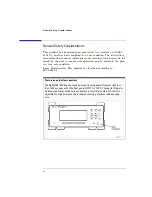
Page 6: ...nsure safe operation and to maintain the prod uct in a safe condition Laser Classification This product is classified according to IEC 60825 1 There is no output laser aperture The Agilent 86120C does not have an output laser aperture However light less than 1 nW escapes out of the front panel OPTICAL INPUT connector Operator maintenance or precautions are not necessary to maintain safety No contr...

Page 7: ...ry cloth or one slightly dampened with water to clean the external case parts Do not attempt to clean internally WA R N IN G This is a Safety Class 1 product provided with protective earth The mains plug shall only be inserted in a socket outlet provided with a protective earth contact Any interruption of the protective conductor inside or outside of theproduct is likely to make theproduct dangero...

Page 8: ...issipated in the cabinet If the total power dissipated in the cabinet is greater than 800 watts then forced convection must be used C A U T IO N Always use the three prong ac power cord supplied with this instrument Failure to ensure adequate earth grounding by not using this cord may cause instrument damage C A U T IO N Do not connect ac power until you have verified the line voltage is correct a...

Page 9: ...gth and Power 3 Changing the Units and Measurement Rate 12 Defining Laser Line Peaks 15 Measuring Laser Separation 18 Measuring Laser Drift 22 Measuring Signal to Noise Ratios 25 Measuring Signal to Noise Ratios with Averaging 29 Measuring Fabry Perot FP Lasers 31 Measuring Modulated Lasers 34 Measuring Total Power Greater than 10 dBm 36 Calibrating Measurements 37 Printing Measurement Results 39 ...

Page 10: ...SYSTem Subsystem 97 TRIGger Subsystem 103 UNIT Subsystem 107 5 Performance Tests Test 1 Absolute Wavelength Accuracy 3 Test 2 Sensitivity 4 Test 3 Polarization Dependence 5 Test 4 Optical Input Return Loss 6 Test 5 Amplitude Accuracy and Linearity 9 6 Specifications and Regulatory Information Definition of Terms 3 Specifications NORMAL Update Mode 5 Specifications FAST Update Mode 8 Operating Spec...

Page 11: ...Contents 3 Contents Menu Maps 4 Error Messages 11 Front Panel Fiber Optic Adapters 17 Power Cords 18 Agilent Technologies Service Offices 18 ...

Page 12: ......

Page 13: ...Power Cable 1 5 Step 3 Connect a Printer 1 6 Step 4 Turn on the Agilent 86120C 1 7 Step 5 Enter Your Elevation 1 8 Step 6 Select Medium for Wavelength Values 1 9 Step 7 Turn Off Wavelength Limiting 1 10 Returning the Instrument for Service 1 11 Getting Started ...

Page 14: ...INE switch disconnects the mains circuits from the mains supply after the EMC filters and before other parts of the instrument C A U T IO N Install the instrument so that the LINE switch is readily identifiable and is easily reached by the operator The LINE switch or the detachable power cord is the instrument disconnecting device It disconnects the mains circuits from the mains supply before othe...

Page 15: ...les and accessories The Agilent 86120C s front panel INPUT connector is no exception When you use improper cleaning and handling techniques you risk expensive instrument repairs damaged cables and compromised measurements Before you connect any fiber optic cable to the Agilent 86120C refer to Cleaning Connections for Accurate Measurements on page 2 40 ...

Page 16: ...carrier and the nearest Agilent Technologies sales and service office Agilent Technologies will arrange for repair or replacement of damaged or incomplete shipments without waiting for a settlement from the transportation company Notify the Agilent Technologies customer engineer of any problems 2 Make sure that the serial number and options listed on the instrument s rear panel label match the ser...

Page 17: ...ng AC power cord supplied with this instrument Failure to ensure adequate earth grounding by not using this cord may cause instrument damage C A U T IO N Do not connect ac power until you have verified the line voltage is correct as described in the following paragraphs Damage to the equipment could result C A U T IO N This instrument has autoranging line voltage input Be sure the supply voltage i...

Page 18: ...the instrument also has a right angle connector so that the Agilent 86120C can be used while sitting on its rear feet You can order additional ac power cables for use in different geographic areas Refer to Power Cords on page 7 18 Step 3 Connect a Printer The Agilent 86120C can print hardcopies of measurement results on a printer The output is ASCII text If you don t have a printer continue with S...

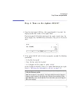
Page 19: ...s to turn on properly consider the following possibilities Is the line fuse good Does the line socket have power Is it plugged into the proper ac power source If the instrument still fails return it to Agilent Technologies for repair Refer to Returning the Instrument for Service on page 1 11 Instrument firmware version When the instrument is first turned on the display briefly shows the instrument...

Page 20: ...ress the Setup key 2 Press the MORE softkey 3 Press the CAL softkey 4 Press ELEV 5 Use the and softkeys to enter the elevation in meters Entries jump in 500 meter steps from 0 m to 5000 m The elevation value selected with the softkeys must be within 250 meters of the actual elevation 6 Press RETURN to complete the entry Converting feet to meters If you know your elevation in feet you can convert t...

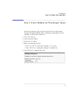
Page 21: ... two mediums vacuum and standard air 1 Press the Setup key 2 Press the MORE softkey 3 Press the CAL softkey 4 Make the following selection Press VACUUM for wavelength readings in a vacuum Press STD AIR for wavelength readings in standard air 5 Press RETURN to complete the entry Definition of standard air Standard air is defined to have the following characteristics Barometric pressure 1013 mbar Te...

Page 22: ...86120C wavelength range of 1270 1650 nm If a user defined wavelength range limit was set using WL LIM the following procedure will ensure that responses across the full wavelength are measured by returning the instrument to its preset state 1 Press the Setup key 2 Press the WL LIM softkey 3 Press LIM OFF to remove the limits on wavelength range ...

Page 23: ... 447 7278 If the instrument is still under warranty or is covered by an Agilent Technologies maintenance contract it will be repaired under the terms of the warranty or contract the warranty is at the front of this man ual If the instrument is no longer under warranty or is not covered by an Agilent Technologies maintenance plan Agilent Technologies will notify you of the cost of the repair after ...

Page 24: ...me and return address Name and phone number of technical contact person Model number of returned instrument Full serial number of returned instrument List of any accessories returned with instrument 2 Cover all front or rear panel connectors that were originally covered when you first received the instrument C A U T IO N Cover electrical connectors to protect sensitive components from electrostati...

Page 25: ...the instrument for packing material and strong enough to accommodate the weight of the instrument Surround the equipment with approximately 7 cm 3 inches of pack ing material to protect the instrument and prevent it from moving in the carton If packing foam is not available the best alternative is S D 240 Air Cap from Sealed Air Corporation Commerce Califor nia 90001 Air Cap looks like a plastic s...

Page 26: ...1 14 Getting Started Returning the Instrument for Service ...

Page 27: ...1 15 Getting Started Returning the Instrument for Service ...

Page 28: ......

Page 29: ...layed units 2 12 Measurement rate 2 13 Continuous or single measurements 2 14 Defining Laser Line Peaks 2 15 Measuring Laser Separation 2 18 Channel separation 2 19 Measuring flatness 2 21 Measuring Laser Drift 2 22 Measuring Signal to Noise Ratios 2 25 Measuring Signal to Noise Ratios with Averaging 2 29 Measuring Fabry Perot FP Lasers 2 31 Measuring Modulated Lasers 2 34 Measuring Total Power Gr...

Page 30: ...d to be less than 5 GHz If you change the elevation where you will be using your Agilent 86120C refer to Calibrating Measurements on page 2 37 Press the green Preset key to return the Agilent 86120C to its default state C A U T IO N Do not exceed 18 dBm source power The Agilent 86120C s input circuitry can be damaged when total input power exceeds 18 dBm You can measure power levels that are great...

Page 31: ...eak wavelength List by wavelength or power Average wavelength and total power If the measured amplitudes are low clean the front panel OPTICAL INPUT connector This section includes Peak WL mode 2 4 List by WL or Power modes 2 6 Total power and average wavelength 2 7 Limiting the wavelength measurement range 2 8 Measuring broadband devices and chirped lasers 2 9 Graphical display of optical power s...

Page 32: ... 2 1 Display after Peak WL key pressed In addition to the digital readouts there is a power bar It provides a convenient analog meter movement for tuning laser power Although the Peak WL mode shows one signal at a time softkeys are provided that allow you to scroll through and display all the measured laser lines You can scroll through the list according to the wave lengths or powers measured To d...

Page 33: ...To move the cursor to view other signals press PREV WL to select next previous shorter wavelength NEXT WL to select next longer wavelength PEAK to signal with greatest power PREV PK to select next lower power signal NEXT PK to select next higher power signal ...

Page 34: ...ignals are ordered according to wavelength BY WL or power BY PWR The cursor shows the currently selected laser line As you scroll through the responses the current position of the selection cursor is shown along the screen s right side Figure 2 2 Display after List by WL key pressed Also notice that power bars graphically show the relative power levels between laser lines To display multiple laser...

Page 35: ...otal input power to the instrument It is the sum of the powers of each laser line it is not a measure of the average power level of the laser lines The following equation shows how individual wavelengths of laser lines are summed together to obtain the average wavelength value where n is the number of laser lines included in the average Pi is the peak power of an individual laser line Power units ...

Page 36: ...cted wavelength units If wavelength units are later changed the start and stop wavelength units will change accordingly Note that a start wavelength limit in nm will become a stop wavelength limit if THz or cm 1 is chosen See To change the units of measure on page 2 12 The graphical display uses the start and stop wavelength values to plot the power spectrum whether the wavelength limit function i...

Page 37: ...h based upon the center of mass of the power spectrum The peak excursion function is used to determine the value of the integra tion limits Care must be taken to ensure that the integration limits are above any noise This is especially true when measuring devices with sloping noise floors like an EDFA amplifier For more informa tion on peak excursion refer to Defining Laser Line Peaks on page 2 15...

Page 38: ...er Offset value In most cases the noise floor will be visible if the total input power is greater than about 5 dBm The Agilent 86120C graphical display The Peak Threshold value is displayed as a dotted line All peaks above this dotted line are displayed in the List by Wavelength and List by Power modes All peaks below this line are not displayed Adjust the Peak Threshold value with the Setup key a...

Page 39: ...n when an instrument state is saved it is off when that state is recalled To save an instrument state 1 Press the Setup key 2 Press the SAV RCL softkey 3 Press the SAVE softkey 4 Press one of the four SAVE softkeys to save the instrument state To recall an instrument state 1 Press the Setup key 2 Press the SAV RCL softkey 3 Press the RECALL softkey 4 Press one of the four RCL softkeys to recall an...

Page 40: ... section includes Displayed units 2 12 Measurement rate 2 13 Continuous or single measurements 2 14 Displayed units As described below it s easy to change the wavelength and amplitude units You can choose between the following units To change the units of measure 1 Press Setup 2 Press the MORE softkey 3 Press the UNITS softkey Table 2 1 Available Units Wavelength Frequency Power nm dBm cm 1 mW THz...

Page 41: ...ximately two times per second This reduces both wavelength resolution and accu racy but can be beneficial in some applications The instrument resolution in NORMAL update mode is 7 GHz 0 06 nm at 1550 nm This resolution is useful when measuring closely spaced laser lines carrying data at up to 5 Gb s rates The instrument resolution in FAST update mode is 14 GHz 0 12 nm at 1550 nm This resolution is...

Page 42: ...is displayed in the display s upper right corner When you switch between normal and fast update modes the rate that the asterisk blinks changes You can specify that the instrument perform a measurement only when the front panel Single key is pressed This is the single acquisition measurement mode and it is useful for capturing and preserving data After capturing the data you can display it using m...

Page 43: ...ak threshold value from the power of the largest laser line So if the largest laser line is 2 dBm and the peak threshold value is 10 dB the peak threshold limit is 8 dBm You can set the peak threshold value between 0 to 40 dB The peak threshold s default value is 10 dB This ensures that any modulated signals being measured are not confused with their AM sidebands For unmodulated lasers or Fabry Pe...

Page 44: ...gnals In the following figure three laser lines are identified responses 1 3 and 4 Response 2 is not identified because it is below the peak threshold The portion of each signal that is within the peak excursion limits is shown in bold lines Because of the peak excursion rule responses 4 and 5 are identified as one laser line the minimum point between 4 and 5 does not drop to the peak excursion li...

Page 45: ...entified The default value is 10 dB Pressing the green PRESET key changes the peak excursion and peak threshold values to their default settings It also turns wavelength range limiting on Turning the Agilent 86120C s power off and then on does not change these settings If too many lines are identified If the following message is displayed too many laser lines have been identified E15 MAX NUMBER OF...

Page 46: ... multiplexed WDM systems where channel spacing must be adhered to The Agilent 86120C can display the wavelength and ampli tude of any laser line relative to another In fact the following types of relative measurements can be made compared to the reference Relative wavelength absolute power Relative power absolute wavelength Relative wavelength and power This section includes Channel separation 2 1...

Page 47: ...47 nm laser line is selected as the reference It is shown in absolute units The wavelengths and powers of the remaining responses are shown relative to this refer ence For example the first response is 2 596 nm below the reference To determine channel spacing simply read the relative wavelength measurement of the laser lines immediately preceding and following the reference Use the and SELECT soft...

Page 48: ...se the Off key to turn off the measurement 4 Select the type of separation to observe WL displays channel separation WL PWR displays both channel separation and differences in power 5 Use the and softkeys to select the reference laser line 6 Press SELECT Press SELECT at any time to select a new reference Press RESET at any time to turn off the delta calculation ...

Page 49: ...m flatness Press RESET to turn off the delta calculations so that all responses are shown in absolute wavelength and powers To measure flatness 1 Press the front panel Preset key 2 Press List by Power This lists the input signals by power with the largest response listed first 3 Press the Delta On key 4 Select PWR 5 Use the and softkeys to select the first laser line 6 Press SELECT 7 Since the lar...

Page 50: ...ative to itself This allows the Agilent 86120C to be used for laser transmitter evaluation burn in or development In addition you can monitor system performance over time temperature or other condition The following display shows power and wavelength drift measured on five laser lines The DRIFT annotation item 1 tells you that drift mea surements are being performed The current relative drift valu...

Page 51: ... the test was begun or the RESET softkey was pressed Display shows absolute maximum values since the drift measurement was started This measurement gives the longest wavelength and greatest power measured The laser line of interest may have since drifted to a lesser value Note that the If measurement updating stops or the values become blanked If in the middle of a measurement the number of laser ...

Page 52: ...ift from the reference since the drift measurement was started Values represent the minimum wavelength and power drift values subtracted from the maximum drift values 5 In the List by WL and List by Power displays use the and softkeys to view the reference values wavelength and power values of each laser line before the test was started During the measurement you can change the display mode to Pea...

Page 53: ...ng figure has a signal to noise ratio of 30 0 dB Signal to noise display During a signal to noise measurement the absolute power of the car rier in dBm is compared to the absolute power of the noise at the carrier wavelength See the following figure The noise power at the carrier must be determined by interpolation because the carrier in most cases can not or should not be turned off You can selec...

Page 54: ...way between the two channels and an equal distance to the other side of the signal of interest See points Pn1 and Pn2 in the following figure If the closest signal is more than 200 GHz from the signal of interest or if there is no other signals present then the noise power is mea sured at 100 GHz on either side of the signal of interest The two mea sured noise power levels are then averaged to est...

Page 55: ...or than a narrow bandwidth the Agilent 86120C normalizes all noise power measurements to a bandwidth of 0 1 nm The annotation 0 1 nm is displayed to show that the noise bandwidth is being normalized to a 0 1 nm bandwidth Repetitive data formats The Agilent 86120C signal to noise application works best when the laser being tested is not modulated or modulated with non repetitive data formats With r...

Page 56: ...ing steps a Press WL REF and press AUTO to let the instrument interpolate the wavelength or press USER to select the last wavelength manually entered b If you chose USER you can specify the wavelength by pressing USER WL Use the softkey to select the digit that requires editing Use the and softkeys to change the value c Press RETURN 5 While the signal to noise measurements are displayed you can pr...

Page 57: ...l remain approximately con stant If however the true signal to noise is below the instrument sensitivity of approximately 40 dB in a 0 1 nm noise bandwidth it will not be measured Averaging can also improve the accuracy of measuring signal to noise of unmodulated lasers Signal to noise with averaging display Averaging is performed on the noise not on the wavelength or power of the laser signals Th...

Page 58: ...le measurement mode Then pressing the Cont key will start a completely new measurement Noise bandwidth affects measurement When measuring noise power the Agilent 86120C must account for the noise bandwidth used during the measurement Because noise band width varies with measurement bandwidth a wide bandwidth allows more noise to the Agilent 86120C s detector than a narrow bandwidth the Agilent 861...

Page 59: ...elected wavelength units Refer to Displayed units on page 2 12 to learn how to change the units The number of laser lines included in the measurement results is also listed as shown in the following figure To characterize a Fabry Perot laser 1 Press Appl s 2 Press FP TEST to measure the Fabry Perot laser s characteristics If you want to stop the updating of measurement data with each sweep press S...

Page 60: ... and wavelength of each spectral component are used to calculate the mean wavelength where Po is total power as defined in this section MODE The mean wavelength spacing between the individual spectral components of the laser PEAK The power level of the peak spectral component of the laser The wavelength of the peak spectral component SIGMA An rms calculation of the spectral width of the laser base...

Page 61: ...of laser modes used in the measurements Refer to Defining Laser Line Peaks on page 2 15 for information on the peak threshold and peak excursion settings The peak excursion value in dB can also be used to determine which side modes are included in the measurements To be accepted each trace peak must rise and then fall by at least the peak excursion value about a given spectral component Setting th...

Page 62: ...r Line Peaks on page 2 15 Even when the laser is amplitude modulated the correct wavelength and power is displayed The spurious wavelengths caused by low frequency amplitude modula tion will be located above and below the correct wavelength by the fol lowing wavelength spacing where F is the modulation frequency in Hz and λ is the correct wave length in nm For example an amplitude modulation of 10...

Page 63: ...us wavelengths will be dis played using preset instrument conditions The preset condition includes peak excursion peak threshold and wavelength range limit ing However increasing peak threshold can cause spurious wave lengths to be displayed Even when the laser being tested is modulated with repetitive formats the carrier s correct wavelength and power is displayed the wave length and power of the...

Page 64: ...d to the Agilent 86120C before damage occurs is 18 dBm The maximum total input power that can be measured is 10 dBm To measure total power exceeding 10 dBm 1 Connect an optical attenuator between the front panel OPTICAL INPUT connector and the fiber optic cable The attenuator must reduce the total input power to the Agilent 86120C so that it is below 10 dBm 2 Press Setup MORE CAL and then PWR OFS ...

Page 65: ...ou must calibrate the Agilent 86120C by entering the elevation Elevations from 0 to 5000 meters can be entered The eleva tion correction is immediately applied to the current measurement even if the instrument is in the single measurement acquisition mode Annotation on the display shows the current calibration elevation in meters and whether the wavelength measurements are shown for a vacuum VAC o...

Page 66: ... the elevation value selected with the softkeys must be within 250 meters of the actual elevation 6 Press RETURN to complete the entry To select the medium for light 1 Press the Setup key 2 Press the MORE softkey 3 Press the CAL softkey and make the following selection Press VACUUM for wavelengths in a vacuum Press STD AIR for wavelengths in standard air 4 Press RETURN to complete the entry Conver...

Page 67: ...n the settings of the instrument when the Print key is pressed The following is an example of a typical printout Agilent 86120C SER US39400020 Firmware Ver 1 000 List By Wavelength 8 Lines Power Offset 0 0 dB Vacuum Elevation 0 Meters Update Normal Peak Excursion 15 dB Peak Threshold 10 dB Device Narrow Input Wavelength Power 1280 384nm 16 97dBm 1281 473 13 14 1282 569 13 92 1283 651 13 34 1284 75...

Page 68: ...n of the fiber optic connector The differences in connector types are mainly in the mechanical assembly that holds the ferrule in position against another identical ferrule Connectors also vary in the polish curve and concentricity of the core within the cladding Mating one style of cable to another requires an adapter Agilent Technologies offers adapters for most instruments to allow testing with...

Page 69: ...for fiber optic applications While not the highest performing connector it represents a good compromise between performance reliability and cost If properly maintained and cleaned this connector can withstand many repeated connections However many instrument specifications require tighter tolerances than most connectors including the FC PC style can deliver These instruments cannot tolerate connec...

Page 70: ...ction of the Diamond HMS 10 connector The nickel silver allows an active centering process that permits the glass fiber to be moved to the desired position This process first stakes the soft nickel silver to fix the fiber in a near center location then uses a post active staking to shift the fiber into the desired posi tion within 0 2 µm This process plus the keyed axis allows very pre cise core t...

Page 71: ...e end of the fiber any stray particles or finger oil can have a significant effect on connector performance Where many repeat connections are required use of a connector saver or patch cable is recommended Figure 2 6 shows the end of a clean fiber optic cable The dark circle in the center of the micrograph is the fiber s 125 µm core and cladding which carries the light The surrounding area is the ...

Page 72: ...hieve the best possible performance when making measurements on a fiber optic system Never use metal or sharp objects to clean a connector and never scrape the connector Avoid matching gel and oils Figure 2 6 Clean problem free fiber end and ferrule Figure 2 7 Dirty fiber end and ferrule from poor cleaning ...

Page 73: ...ge and continued use of a damaged fiber can transfer damage to the instrument When inserting a fiber optic cable into a connector gently insert it in as straight a line as possible Tipping and inserting at an angle can scrape material off the inside of the connector or even break the inside sleeve of connectors made with ceramic material When inserting a fiber optic connector into a connector make...

Page 74: ...onnections Since return loss and inser tion loss are key factors in determining optical connector performance they can be used to determine connector degradation A smooth pol ished fiber end should produce a good return loss measurement The quality of the polish establishes the difference between the PC phys ical contact and the Super PC connectors Most connectors today are physical contact which ...

Page 75: ... IN G Always remove both ends of fiber optic cables from any instrument system or device before visually inspecting the fiber ends Disable all optical sources before disconnecting fiber optic cables Failure to do so may result in permanent injury to your eyes Cleaning Connectors The procedures in this section provide the proper steps for cleaning fiber optic cables and Agilent Technologies univers...

Page 76: ... to clean optical fiber ends Foam swabs can leave filmy deposits on fiber ends that can degrade performance 1 Apply pure isopropyl alcohol to a clean lint free cotton swab or lens paper Cotton swabs can be used as long as no cotton fibers remain on the fiber end after cleaning 2 Clean the ferrules and other parts of the connector while avoiding the end of the fiber 3 Apply isopropyl alcohol to a n...

Page 77: ...e air Refer to instructions provided on the compressed air canister 7 As soon as the connector is dry connect or cover it for later use If the performance after the initial cleaning seems poor try cleaning the connector again Often a second cleaning will restore proper per formance The second cleaning should be more arduous with a scrub bing action To clean an adapter The fiber optic input and out...

Page 78: ...ighs the risk of contamination by foam swabs 2 Clean the adapter with the foam swab 3 Dry the inside of the adapter with a clean dry foam swab 4 Blow through the adapter using filtered dry compressed air Nitrogen gas or compressed dust remover can also be used Do not shake tip or invert compressed air canisters because this releases par ticles in the can into the air Refer to instructions provided...

Page 79: ...itoring the Instrument 3 16 Status registers 3 17 Queues 3 22 Reviewing SCPI Syntax Rules 3 23 Example Programs 3 28 Example 1 Measure a DFB laser 3 30 Example 2 Measure WDM channels 3 32 Example 3 Measure WDM channel drift 3 34 Example 4 Measure WDM channel separation 3 37 Example 5 Measure signal to noise ratio of each WDM channel 3 39 Example 6 Increase a source s wavelength accuracy 3 41 Lists...

Page 80: ...orial Description of Hewlett Packard Interface Bus 1987 Hewlett Packard Company SCPI Standard Commands for Program mable Instruments 1995 International Institute of Electrical and Electronics Engineers IEEE Standard 488 1 1987 IEEE Standard Digital Interface for Programma ble Instrumentation New York NY 1987 International Institute of Electrical and Electronics Engineers IEEE Standard 488 2 1987 I...

Page 81: ... For example if the instrument is first placed in local lockout mode and then placed in remote mode no softkeys are displayed Consult the documentation for your programming environment to determine which commands are used to put an instrument in the remote and local lockout modes These are not Agilent 86120C com mands they control GPIB control lines and do not send any characters to the Agilent 86...

Page 82: ...n Preset key does not change the GPIB address Set single acquisition mode An advantage of using the RST command is that it sets the Agilent 86120C into the single measurement acquisition mode Because the READ and MEASure data queries expect this mode their proper operation is ensured To change the GPIB address 1 Press the Setup key 2 Press MORE twice then GPIB 3 Use the and softkeys to change the ...

Page 83: ... section it configures or queries data from Notice that there are two buffers from which data can be queried an uncorrected data buffer and a corrected data buffer With each scan of the input wavelength range the analog to digital converter loads 65 536 data values into the uncorrected data buffer This is considered to be one measurement A fast update measurement mode is avail able for quicker mea...

Page 84: ...Mit START and progresses toward WLIMit STOP These peak values are then placed into the corrected data buffer Each peak value consists of an amplitude and wavelength measurement Amplitude and wavelength correction factors are applied to this data For a listing of the programming commands including a cross refer ence to front panel keys refer to the following tables Table 3 10 Programming Commands o...

Page 85: ...rints measurement results SENSe Sets elevation correction values selects readings for air or vacuum and enters amplitude offsets Queries time domain values of the input data STATus Queries instrument status registers SYSTem Presets Agilent 86120C and queries error messages TRIGger Stops current measurement Acquires new measurement data Also used to select single or continuous acquisition of measur...

Page 86: ...enumber or Frequency CALCulate2 PWAVerage STATe CALCulate2 DATA Total Power W dBm CALCulate2 PWAVerage STATe CALCulate2 DATA Fabry Perot Laser CALCulate3 FPERot Refer to FPERot STATE on page 4 62 Laser Line Separation CALCulate3 DELTa REFerence CALCulate3 DATA Laser Line Drift CALCulate3 DRIFt STATe CALCulate3 DATA Signal to Noise Ratio CALCulate3 SNR STATe CALCulate3 DATA Signal to Noise Ratio Av...

Page 87: ...ngest wavelength send the following command MEASure SCALar POWer WAVelength MAX Specifying SCALar places the display in the single wavelength format and returns a single value to the computer Specifying ARRay places the display in the List by Power or List by WL modes an array of data is returned to the computer Table 2 5 The Different Forms of MEASure Desired Measurement Data Use this MEASure Que...

Page 88: ...send the READ command when the instrument is in the continuous measurement acquisition mode Because READ contains an INIT IMM command which expects the single measurement acquisition mode an error is generated and the INIT command is ignored FETCh command The FETCh command returns data from previously performed mea surements it does not initiate the collection of new data Because FETCh does not co...

Page 89: ...eried The query returns the last configuration setup by the CONFigure command The instrument returns a string which is the last instrument function sent by a CONFigure command or MEASure query The returned string is in the short command form Use caution when using this query because if any instrument settings were changed since the last CONFigure command or MEASure query these changes may not be i...

Page 90: ...Culate2 WLIMit STARt WNUMber CALCulate2 WLIMit STOP FREQuency CALCulate2 WLIMit STOP WAVelength CALCulate2 WLIMit STOP WNUMber CALCulate3 SNR AUTO SENSe CORRection ELEVation INITiate CONTinuous INITiate IMMediate The following additional commands are also non sequential commands if CALCulate3 SNR AUTO is set to OFF CALCulate3 REFerence FREQuency CALCulate3 REFerence WAVelength CALCulate3 REFerence...

Page 91: ...hen send an INIT IMM command The following program ming fragment results in an error 213 Init ignored This occurs because the ELEVation command causes the recalculation of the data which is like sending the INIT IMM command When the actual INIT IMM is sent the error occurs because the command is already in progress OUTPUT 720 INIT IMM OUTPUT 720 SENSe CORRection ELEVation 1000 OUTPUT 720 INIT IMM ...

Page 92: ...f you select a drift measurement you can select one of the following additional states CALC3 DRIF DIFF STAT difference CALC3 DRIF MAX STAT maximum drift CALC3 DRIF MIN STAT minimum drift CALC3 DRIF REF STAT drift reference values The CALCulate3 DRIFt PRESet command turns off the minimum max imum difference and reference states but leaves the drift state on Attempting to turn more than one state on...

Page 93: ...rned in the string The string does not contain a first value which specifies the string length This is shown in the following example OUTPUT 720 CALCulate1 POINts ENTER 720 Length OUTPUT 720 CALCulate1 DATA ENTER 720 Result Data can be corrected for elevation and vacuum Normally the Agilent 86120C provides measurement values calculated for conditions in air at sea level Use the SENSe CORRection EL...

Page 94: ...g execu tion or command errors and determining whether or not measure ments have been completed Several status registers and queues are provided to accomplish these tasks In this section you ll learn how to enable and read these registers In addition to the information in this section you should review the com mands documented in Common Commands on page 4 3 and STATus Subsystem on page 4 90 ...

Page 95: ...hich indicate the status of the other two regis ters OPERation Status Contains bits that report on the instrument s normal operation QUEStionable Status Contains bits that report on the condition of the sig nal Status Byte register The Status Byte Register contains summary bits that monitor activity in the other status registers and queues The Status Byte Register s bits are set and cleared by the...

Page 96: ...3 18 Programming Monitoring the Instrument ...

Page 97: ...ct the logic transitions which set bits in the OPERation Status and QUEStionable Status registers For example you can define the POWer bit of the QUEStionable Status register to report an event when the condition transitions from false to true This is a positive transition You can also specify a negative transition where the bit is set when the condition transitions from true to false Table 3 6 Bi...

Page 98: ...t Status Register can be read and the register cleared by sending the ESR query The value returned is the total bit weights of all of the bits that are set at the present time Table 3 7 Bits in Questionable Status Register Bit Definition 0 1 and 2 not used 3 POWer indicating that the instrument is measuring too high of a power 3 through 8 not used 9 Maximum signals indicating that the instrument h...

Page 99: ...or the output queue is also cleared In addition the request for the OPC bit is also cleared For example suppose your application requires an interrupt whenever any type of error occurs The error related bits in the Standard Event Status Register are bits 2 through 5 The sum of the decimal weights of these bits is 60 Therefore you can enable any of these bits to generate the summary bit by sending ...

Page 100: ...indicated by positive values General errors have negative values You can clear the error queue by reading its contents sending the CLS command or by cycling the instrument s power The error queue is first in first out If the error queue overflows the last error in the queue is replaced with error 350 Queue overflow Any time the queue overflows the least recent errors remain in the queue and the mo...

Page 101: ...Simply create a com mand string from the commands listed in this book and place the string in your program language s output statement For commands other than common commands include a colon before the subsystem name For example the following string places the cursor on the peak laser line and returns the power level of this peak OUTPUT 720 MEAS SCAL POW MAX Use either short or long forms Commands...

Page 102: ...length of the keyword is exactly four char acters You can use upper or lowercase letters Program headers can be sent using any combination of uppercase or lowercase ASCII characters Instrument responses however are always returned in uppercase Combine commands in the same subsystem You can combine commands from the same subsystem provided that they are both on the same level in the subsystem s hie...

Page 103: ...pe of command is received within a program message you must reenter the original subsystem after the command Adding parameters to a command Many commands have parameters that specify an option Use a space character to separate the parameter from the command as shown in the following line OUTPUT 720 INIT CONT ON Separate multiple parameters with a comma Spaces can be added around the commas to impr...

Page 104: ...numbers are all equal 28 0 28E2 280E 1 28000m 0 028K 28E 3K If a measurement cannot be made no response is given and an error is placed into the error queue For example RST FETCh POW will timeout the controller and place a Data stale or corrupt error in the error queue Table 3 9 Suffix Multipliers Multiplier Mnemonic 1E18 EX 1E15 PE 1E12 T 1E9 G 1E6 MA 1E3 K 1E 3 M 1E 6 U 1E 9 N 1E 12 P 1E 15 F 1E...

Page 105: ...nstrument places the answer in its output queue The answer remains in the output queue until it is read or another command is issued For example the query OUTPUT 720 CALCULATE2 POINTS places the number of points in the data set in the output queue In HP BASIC the controller input statement ENTER 720 Range passes the value across the bus to the controller and places it in the variable Range A newli...

Page 106: ... and how to return data to the computer All of the examples are written in the HP BASIC programming lan guage Many subroutines are repeated in the examples The first five example programs contain several common subroutines These routines along with one function are described in the rest of this introduction The descriptions are listed in the general order that the subroutines are called in the pro...

Page 107: ...ic test in the subroutine tests for the same event status register bits enabled by the Set_ese subroutine BIT Cme 5 BIT Cme 4 BIT Cme 2 This subroutine is called in Examples 1 through 5 However it is mod ified in Examples 3 4 and 5 to allow it to indicate the last program ming command that was sent to the instrument before an error occurred This is accomplished by adding an optional argument strin...

Page 108: ...Instrument Mwm ASSIGN Mwm TO 720 Set_ese PRINT USING 37A 33A Multi Wavelength Meter Identity is FNIdentity OUTPUT Mwm INIT CONT OFF ON TIMEOUT 7 5 CALL Err_mngmt OUTPUT Mwm MEAS SCAL POW WAV ENTER Mwm Current_wl OUTPUT Mwm FETC SCAL POW ENTER Mwm Current_pwr OFF TIMEOUT PRINT USING 20A 4D 3D 3A 19A M2D 2D 4A The wavelength is Current_wl 1 0E 9 nm with a power of Current_pwr dBm END Err_mngmt SUB E...

Page 109: ...1 Programming Example Programs Identity DEF FNIdentity COM Instrument MwmV DIM Identity 50 Identity OUTPUT Mwm RST OUTPUT Mwm OPC ENTER Mwm Opc_done OUTPUT Mwm IDN ENTER Mwm Identity RETURN Identity FNEND ...

Page 110: ...n this program COM Instrument Mwm ASSIGN Mwm TO 720 ON ERROR GOTO Error_msg Set_ese PRINT USING 37A 33A Multi Wavelength Meter Identity is FNIdentity OUTPUT Mwm INIT CONT OFF ON TIMEOUT 7 5 CALL Err_mngmt OUTPUT Mwm MEAS ARR POW WAV ENTER Mwm USING K Nb_wl ALLOCATE Current_wl 1 Nb_wl ENTER Mwm USING K Current_wl OUTPUT Mwm FETC ARR POW ENTER Mwm USING K Nb_wl ALLOCATE Current_pwr 1 Nb_wl ENTER Mwm...

Page 111: ...D NOT BIT Cme 5 AND Err 0 Subend SUBEND Set_ese SUB Set_ese COM Instrument Mwm OUTPUT Mwm ESE IVAL 00110100 2 SUBEND Identity DEF FNIdentity COM Instrument Mwm DIM Identity 50 Identity OUTPUT Mwm RST OUTPUT Mwm OPC ENTER Mwm Opc_done OUTPUT Mwm IDN ENTER Mwm Identity RETURN Identity FNEND ...

Page 112: ...e intro duction to this section for a description of each subroutine that is contained in this program COM Instrument Mwm ASSIGN Mwm TO 720 DIM Key 1 ON ERROR GOTO Error_msg Set_ese PRINT USING 37A 33A Multi Wavelength Meter Identity is FNIdentity ON TIMEOUT 7 5 CALL Err_mngmt Cmd_opc RST Cmd_opc INIT IMM Cmd_opc OPC Cmd_opc CONF ARR POW WAV Turn on the drift calculation Cmd_opc CALC3 DRIF STAT ON...

Page 113: ...LC3 DATA POW ENTER Mwm USING K Current_diff_pw OFF TIMEOUT FOR I 1 TO Nb_pt PRINT USING 18A 2D 6A M4D 2DE 3A 21A MDD 3DE 3A Wavelength number I is Current_ref_wl I m with a drift from Current_diff_wl I m PRINT USING 28A SDD 2DE 4A 20A MDD 3DE 3A it has a power level of Current_ref_pwr I dBm with a drift from Current_diff_pw I dB NEXT I STOP Error_msg PRINT The program is aborted due to ERRM END Er...

Page 114: ...OM Instrument Mwm DIM Identity 50 Identity OUTPUT Mwm RST OUTPUT Mwm OPC ENTER Mwm Opc_done OUTPUT Mwm IDN ENTER Mwm Identity RETURN Identity FNEND Cmd_opc SUB Cmd_opc Set_cmd COM Instrument Mwm OUTPUT Mwm Set_cmd OUTPUT Mwm OPC ENTER Mwm Opc_done SUBEND Tempo SUB Tempo Temp FOR I Temp TO 0 STEP 1 DISP Waiting for VAL I sec WAIT 1 NEXT I DISP SUBEND ...

Page 115: ...lti Wavelength Meter Identity is FNIdentity ON TIMEOUT 7 5 CALL Err_mngmt Cmd_opc RST Change to list by wavelength display Cmd_opc CONF ARR POW WAV Trigger and wait for one measurement Cmd_opc INIT Cmd_opc WAI Turn on delta mode Cmd_opc CALC3 DELT WPOW STAT ON Set first wavelength as reference Cmd_opc CALC3 DELT REF WAV MIN Query number of data points OUTPUT Mwm CALC3 POIN ENTER Mwm USING K Nb_pt ...

Page 116: ...D Err_mngmt SUB Err_mngmt OPTIONAL Cmd_msg COM Instrument Mwmt DIM Err_msg 255 INTEGER Cme CLEAR Mwm REPEAT OUTPUT Mwm ESR ENTER Mwm Cme OUTPUT Mwm SYST ERR ENTER Mwm Err_msg IF NPAR 0 AND NOT POS Err_msg 0 THEN PRINT This command Cmd_msg makes the following error IF NOT POS Err_msg 0 THEN PRINT Err_msg UNTIL NOT BIT Cme 2 AND NOT BIT Cme 4 AND NOT BIT Cme 5 AND POS Err_msg 0 Subend SUBEND Set_ese...

Page 117: ...ength Meter Identity is FNIdentity ON TIMEOUT 7 5 CALL Err_mngmt Cmd_opc RST OUTPUT Mwm MEAS ARR POW WAV ENTER Mwm USING K Nb_pt ALLOCATE Current_wl 1 Nb_pt ENTER Mwm USING K Current_wl OUTPUT Mwm FETC ARR POW ENTER Mwm USING K Nb_pt ALLOCATE Current_pwr 1 Nb_pt ENTER Mwm USING K Current_pwr Turn signal to noise ratio on Cmd_opc CALC3 SNR STAT ON Err_mngmt CALC3 SNR STAT ON Set first wavelength as...

Page 118: ... OUTPUT Mwm SYST ERR ENTER Mwm Err_msg IF NPAR 0 AND NOT POS Err_msg 0 THEN PRINT This command Cmd_msg makes the following error IF NOT POS Err_msg 0 THEN PRINT Err_msg UNTIL NOT BIT Cme 2 AND NOT BIT Cme 4 AND NOT BIT Cme 5 AND POS Err_msg 0 Subend SUBEND Set_ese SUB Set_ese COM Instrument Mwm OUTPUT Mwm ESE IVAL 00110100 2 SUBEND Identity DEF FNIdentity COM Instrument Mwm DIM Identity 50 Identit...

Page 119: ...e Agilent 86120C s absolute accuracy at 1550 nm In order to run this program the tunable laser source s firmware must support the automatic alignment command WAVEACT The program uses the following measurement algorithm Identify and initialize the Agilent 86120C and tunable laser source Ask user for desired wavelength Set wavelength of tunable laser source Turn tunable laser source s output on Ente...

Page 120: ...T What wavelength nm do you wish to have Target_wl Target_wl Target_wl 1 OE 9 PRINT the target wavelength is Target_wl Set wavelength of tunable laser source OUTPUT Tls WAVE VAL Target_wl OUTPUT Tls OUTP ON Enter realignment loop REPEAT OUTPUT Mwm MEAS SCAL POW WAV ENTER Mwm Current_wl PRINT The current wavelength is VAL Current_wl Diff_wl PROUND ABS Target_wl Current_wl 16 PRINT Diff between targ...

Page 121: ...s a saved instrument state RST Resets instrument SAV Saves an instrument state SRE Sets bits in service request enable register STB Queries value of status byte TRG Triggers acquisition of measurement data TST Performs an instrument self test WAI Causes instrument to finish processing current command before continuing Measurement Instructions CONFigure Configures instrument for wavelength wavenumb...

Page 122: ...te2 WLIMit STARt WNUMber Sets the starting wavenumber for the wavelength limit range I CALCulate2 WLIMit STOP FREQuency Sets the stopping frequency for the wavelength limit range I CALCulate2 WLIMit STOP WAVelength Sets the stopping wavelength for the wavelength limit range I CALCulate2 WLIMit STOP WNUMber Sets the stopping wavenumber for the wavelength limit range I CALCulate3 CALC3 Subsystem CAL...

Page 123: ...on and off I CALCulate3 FPERot STATe Turns the Fabry Perot measurement mode on and off I CALCulate3 FPERot MEAN WAVelength Queries the mean wavelength of the selected modes I CALCulate3 FPERot MEAN FREQuency Queries the mean frequency of the selected modes I CALCulate3 FPERot MEAN WNUMber Queries the mean wavenumber of the selected modes I CALCulate3 FPERot PEAK WAVelength Queries the peak wavelen...

Page 124: ...ment reference in the SNR calculation I CALCulate3 SNR REFerence WNUMber Sets the wave number used for the noise measurement reference in the SNR calculation I CALCulate3 SNR STATe Turns the SNR calculation on and off I DISPlay Subsystem DISPlay MARKer MAXimum Sets the marker to the signal with the largest power I DISPlay MARKer MAXimum LEFT Moves marker to signal with the next lower wavelength or...

Page 125: ...sition filter register S STATus OPERation QUEStionable NTRansit ion Sets the negative transition filter register S STATus PRESet Presets the enable registers for all status nodes S SYSTem Subsystem SYSTem ERRor Queries an error from the error queue S SYSTem HELP HEADers Queries an ASCII listing of all Agilent 86120C remote commands I SYSTem PRESet Performs the equivalent of a front panel PRESET ke...

Page 126: ...Sure ARRay POWer WNUMber Cont INITiate CONTinuous ON DBM UNIT POWer DEVICE SENSe CORRection DEVice DRIFT CALCulate3 DRIFt STATe ELEV SENSe CORRection ELEVation EXIT State dependent FAST See UPDATE FP TEST CALCulate3 FPERot STATe GPIB none List by Power CONFigure ARRay POWer List by WL MEASure ARRay POWer WAVelength MAX MIN CALCulate3 DRIFt MINimum STATe and CALCulate3 DRIFt MAXimum STATe MW UNIT P...

Page 127: ...TATe S N AVG CALCulate3 ASNR STATe SELECT CONFigure POWer Setup See CAL UNITS and UPDATE Single INITiate CONTinuous OFF START WL CALCulate2 WLIMit STARt STOP WL CALCulate2 WLIMit STOP STD AIR SENSe CORRection MEDium AIR THRSHLD See PK EXC and PK THLD THZ MEASure ARRay POWer FREQuency UNITS UNIT POWer UPDATE Measurement Instructions and CALCulate1 TRANsform FREQuency POINts USER CALCulate3 SNR AUTO...

Page 128: ...3 50 Programming Lists of Commands ...

Page 129: ... 4 44 CONFigure Measurement Instruction 4 74 DISPlay Subsystem 4 75 FETCh Measurement Instruction 4 79 HCOPy Subsystem 4 80 MEASure Measurement Instruction 4 81 READ Measurement Instruction 4 82 SENSe Subsystem 4 83 STATus Subsystem 4 90 SYSTem Subsystem 4 97 TRIGger Subsystem 4 103 UNIT Subsystem 4 107 Programming Commands ...

Page 130: ...gle brackets indicate values entered by the programmer Or indicates a choice of one element from a list Square brackets indicate that the enclosed items are optional When several items are enclosed by braces one and only one of these elements must be selected integer An ASCII string representing an integer This is defined by the IEEE 488 2 NR1 format real An ASCII string representing a real number...

Page 131: ...e status byte register Syntax CLS Description With the exception of the output queue all queues that are summa rized in the status byte register are emptied The error queue is also emptied Neither the event status enable register nor the service request enable register are affected by this command After the CLS command the instrument is left in the idle state The command does not alter the instrum...

Page 132: ...ble register is cleared at power on The RST and CLS commands do not change the register The ESE query returns the value of the event status enable register Query Response integer is a mask from 0 to 255 Example OUTPUT 720 ESE 32 In this example the ESE 32 command enables CME event summary bit bit 5 of the event status enable register Therefore when an incor rect programming command is received the...

Page 133: ...ne at the time you read the byte The following table shows each bit in the event status register and its bit weight The register is cleared when it is read Query Response integer ranges from 0 to 255 Example OUTPUT 720 ESR ENTER 720 Event PRINT Event Table 4 14 Standard Event Status Register Bit Bit Weight Condition 7 128 PON Power On 6 64 Not Used 5 32 CME Command Error 4 16 EXE Execution Error 3...

Page 134: ...m message Any queries after the IDN query in a program message are ignored The maximum length of the identification string is 50 bytes Query Response The following identification string is returned The third entry is the instrument s serial number The last entry in the string is the firmware version number this value may vary between instruments Agilent 86120C USaaaabbbb 1 000 Example DIM Id 50 OU...

Page 135: ...o check when the Agilent 86120C has completed the operation Use the OPC query to ensure all operations have completed before continuing the program By following a command with an OPC query and an ENTER statement the program will pause until the response ASCII 1 is returned by the instrument Be sure the computer s timeout limit is at least two seconds since some of the Agilent 86120C commands take ...

Page 136: ...alid and a measurement query such as FETCh results in error number 230 Data corrupt or stale You must ini tiate a new sweep with INIT IMM before you can use the FETCh com mand Table 4 15 Conditions Set by RST Reset 1 of 2 Item Setting Display mode single wavelength Start wavelength 1270 nm Stop wavelength 1650 nm Graphical display off Measurement acquisition single Wavelength calibration vacuum El...

Page 137: ... avg display mode frequency units power units elevation peak excursion peak threshold power Number of uncorrected data points 15 047 Delta Measurements power off wavelength off wavelength and power off reference signal position 1270 nm Drift measurements off Signal to Noise Measurements measurement off wavelength reference auto reference user wavelength 1550 nm in vacuum number of averages count 1...

Page 138: ...n the service request enable register enables the corresponding bit in the status byte register to generate a service request A zero disables the bit The fol lowing table lists the bits in the service request enable register and what they mask The service request enable register is cleared when the instrument is turned on The RST and CLS commands do not change the register The SRE query returns th...

Page 139: ...mmands Common Commands Query Response integer from 0 to 63 or from 128 to 191 Example OUTPUT 720 SRE 32 In this example the command enables ESB event summary bit 5 in the status byte register to generate a service request ...

Page 140: ...tal of the bit weights of all of the bits set to one at the time you read the byte The following table shows each bit in the status byte register and its bit weight The STB query does not affect the contents of the status byte register Query Response integer from 0 to 255 Example OUTPUT 720 STB ENTER 720 Value PRINT Value Table 4 17 Status Byte Register Bit Bit Weight Condition 7 128 Not Used 6 64...

Page 141: ...n error is generated Example The following example starts the data acquisition according to the cur rent settings OUTPUT 720 TRG TST The TST test query starts a self test on the instrument Syntax TST Description The result of the test is placed in the output queue A zero indicates the test passed and a non zero value indicates the test failed The instrument will initiate a measurement and check fo...

Page 142: ...he WAI command prevents the instrument from executing any fur ther commands until the current command has finished executing Syntax WAI Description All pending operations are completed during the wait period This command cannot be issued as a query ...

Page 143: ...wave number measurements When the SCALar command is used data for a single measurement value is returned When the ARRay command is used multiple data values are returned The MEASure measurement instruction always acquires new measure ment data In order to obtain both wavelength and power values from the same measurement data use two FETCh commands This is shown in the following program fragment OU...

Page 144: ...4 16 Programming Commands Measurement Instructions The commands in this subsystem have the following command hierar chy MEASure READ FETCh CONFigure ARRay SCALar POWer FREQuency WAVelength WNUMber ...

Page 145: ...The display is placed in the list by power mode Returned values are in the current power units Wavelength units are not affected expected_value Constants MAXimum Displays the highest power signal MINimum Displays the lowest power signal DEFault Displays the signal at the current marker position Used With expected_value resolution SCALar optional ignored ARRay ignored ignored CONFigure command When...

Page 146: ... line is an example of a returned string when MEAS SCAL POW MAX is sent 5 88346500E 000 If six laser lines are located and MEAS ARR POW is sent the follow ing string could be returned Notice that the first returned number indicates the number of laser line values returned in the query The measurement units are in dBm 6 1 37444400E 001 1 10996100E 001 9 62396600E 000 7 94024500E 000 7 01303200E 000...

Page 147: ...a unitless number whose value will be limited to either 0 01 or 0 001 whichever is closer MAXimum resolution is equivalent to the FAST measurement update mode MINimum resolution is equivalent to the NORMAL measurement update mode Returned values are in Hz display is in THz Power units are not affected expected_value Constants MAXimum The highest frequency signal MINimum The lowest frequency signal...

Page 148: ...MAX FETC SCAL POW FREQ 230 8THZ MIN READ SCAL POW FREQ 230 8THZ MEAS SCAL POW FREQ 230 8THZ Query Response The following line is an example of a returned string when MEAS SCAL POW FREQ MAX is sent 1 94055176E 014 If six laser lines are located and MEAS ARR POW FREQ is sent the following string is an example of the returned data Notice that the first returned number indicates the number of laser li...

Page 149: ... sets the resolution of the measurement It is a unitless number whose value will be limited to either 0 01 or 0 001 whichever is closer Returned values are in meters Displayed units are nanometers Power units are not affected expected_value Constants MAXimum The highest wavelength signal MINimum The lowest wavelength signal DEFault The current marker position Used With expected_value resolution SC...

Page 150: ...C SCAL POW WAV 1300NM MIN READ SCAL POW WAV 1300NM MEAS SCAL POW WAV 1300NM Query Response The following line is an example of a returned string when MEAS SCAL POW WAV MAX is sent 1 5529258E 006 If six laser lines are located and MEAS ARR POW WAV is sent the following string could be returned Notice that the first returned num ber indicates the number of laser line values returned in the query 6 1...

Page 151: ...easurement It is a unitless number whose value will be limited to either 0 01 or 0 001 whichever is closer Returned values are in inverse meters Displayed units are inverse centimeters Power units are not affected expected_value Constants MAXimum The laser line having the largest wave number MINimum The laser line having the smallest wave number DEFault The current marker position Used With expect...

Page 152: ...M 6451 MEAS SCAL POW WNUM 6451 Query Response If the MEAS SCAL POW WNUM 6451 command is sent and a 1550 nm laser line is present the following response would be returned to the computer 6 45286262E 005 Notice that the returned units are m 1 If six laser lines are measured and MEAS ARR POW WNUM is sent the following response is returned Notice that the first returned number indicates the number of ...

Page 153: ...orrected frequency spec trum data In NORMAL measurement update mode 15 047 values are returned If the Agilent 86120C is set for FAST measurement update mode low resolution 7 525 values are returned The commands in this subsystem have the following command hierar chy CALCulate1 DATA TRANsform FREQuency POINts ...

Page 154: ... command or the resolution argument of an instrument function Refer to Measurement Instruc tions on page 4 15 When NORMAL measurement update is specified over 250 kilobytes of data 15 047 values can be returned to the computer When FAST measurement update is specified over 125 kilobytes of data 7 525 val ues can be returned The following string is a typical example of the first few returned val ue...

Page 155: ...137 nm in vacuum When FAST measurement mode is selected the frequency spacing between elements is uniform and is equal to 7 226756 GHz Note the spacing between values is not uniform in wavelength units The values returned are in ascending optical frequency Only the frequency domain data corresponding to 1270 1650 wavelength in vacuum is returned 7 525 values The first value of the uncorrected freq...

Page 156: ...4 28 Programming Commands CALCulate1 Subsystem This query will generate a Settings conflict error if the instrument is in the signal to noise average application ...

Page 157: ...an FFT size of 15 047 A FAST updated display corresponds to an FFT size of 7 525 These val ues are a subset of the uncorrected data buffer shown in the figure that is located in Making Measurements on page 3 5 Changing the number of points causes the instrument to reprocess the current set of data The query form of the command returns the number of points in the data set This is the number of meas...

Page 158: ...4 30 Programming Commands CALCulate1 Subsystem Query Response For normal update 15 047 For fast update 7 525 ...

Page 159: ...LCulate2 commands to query corrected values frequency spectrum data The commands in this subsystem have the following command hierar chy CALCulate2 DATA PEXCursion POINts PTHReshold PWAVerage STATe WLIMit STATe STARt FREQuency WAVelength WNUMber STOP FREQuency WAVelength WNUMber ...

Page 160: ...er line wave numbers after the peak search is completed If CALC2 PWAV STAT is on the power weighted average wave number is returned Attribute Summary Preset State not affected SCPI Compliance standard Query Only Description Use the CALC2 POIN query to determine the number of points the CALC2 DATA query will return The following string is a typical example of the first few returned values when WAVe...

Page 161: ...te Summary Non sequential command Preset State 15 dB RST State 15 dB SCPI Compliance instrument specific Description A laser line is identified as a valid peak if its amplitude is greater than the peak excursion plus the amplitudes of the closest local min ima on either side of the peak This command works in conjunction with the peak threshold setting Refer to PTHReshold on page 4 34 Changing the ...

Page 162: ...nes are located 6 PTHReshold Sets the peak threshold limit used by the instrument to determine valid laser line peaks Syntax CALCulate2 PTHReshold integer MINimum MAXimum DEFault integer represents logarithmic units in dB Valid range is 0 to 40 Constant Value MINimum 0 dB MAXimum 40 dB Non sequential command Always use an OPC query or a WAI command to ensure that this command has the time to compl...

Page 163: ...aser Line Peaks on page 2 15 The query response is the current value For example if the current value is set to 15 dB the following value is returned 15 PWAVerage STATe Places the instrument in the power weighted average mode Syntax CALCulate2 PWAVerage STATe ON OFF 1 0 Attribute Summary Preset State off RST State off Description When the state is on the CALC2 DATA POW query returns the total powe...

Page 164: ...4 36 Programming Commands CALCulate2 Subsystem Turning power weighted average mode on while making delta Fabry Perot or signal to noise measurements results in a 221 Settings con flict error ...

Page 165: ...tion is off the instrument displays peaks over the full wavelength range The graphics display always shows the range between WLIMit STARt and WLIMit STOP regardless of the state of this command Whenever the Agilent 86120C receives this command it reprocesses the data and performs a new peak search Non sequential command Always use an OPC query or a WAI command to ensure that this command has the t...

Page 166: ...ompliance instrument specific Description This command sets the starting range for the wavelength limit in hertz The start frequency value must be less than or equal to the stop fre quency value or the start frequency will be clipped to the stop fre quency and a Data out of range error will be generated The default units for the real parameter are hertz Non sequential command Always use an OPC que...

Page 167: ...tart wavelength value must be less than or equal to the stop wavelength value or the start wavelength will be clipped to the stop wavelength and a Data out of range error will be generated Setting the start wavelength is equivalent to setting the stop frequency wavenumber because of the inverse relationship of frequency to wavelength The default units for the real parameter are meters Non sequenti...

Page 168: ... Compliance instrument specific Description This command sets the starting range for the wavelength limit The default units for the real parameter value are m 1 The start wave number value must be less than or equal to the stop wavenumber value or the start wavenumber will be clipped to the stop wavenumber and a Data out of range error will be generated Non sequential command Always use an OPC que...

Page 169: ...I Compliance instrument specific Description This command sets the stopping range for the wavelength limit The default units for the real parameter are Hz The stop frequency value must be greater than or equal to the start frequency value or the stop frequency will be clipped to the start frequency and a Data out of range error will be generated Non sequential command Always use an OPC query or a ...

Page 170: ...he wavelength limit The default units for the real parameter are meters The stop wavelength value must be greater than or equal to the start wavelength value or the stop wavelength will be clipped to the start wavelength and a Data out of range error will be generated Setting the start wave length is equivalent to setting the start frequency wavenumber because of the inverse relationship of freque...

Page 171: ...ance instrument specific Description This command sets the stopping range for the wavelength limit The default units for the real parameter are inverse meters The stop wavenumber value must be less than or equal to the start wavenumber value or the stop wavenumber will be clipped to the start wavenumber and a Data out of range error will be generated Non sequential command Always use an OPC query ...

Page 172: ...o noise and Fabry Perot measurements The commands in this subsystem have the following command hierarchy CALCulate3 ASNR CLEar COUNt STATe DATA DELTa POWer STATe PRESet REFerence FREQuency POWer WAVelength WNUMber WAVelength STATe WPOWer STATe DRIFt DIFFerence STATe MAXimum STATe MINimum STATe PRESet REFerence RESet STATe STATe ...

Page 173: ...length FREQuency WNUMber MEAN WAVelength FREQuency WNUMber MODE WAVelength FREQuency WNUMber PEAK WAVelength FREQuency WNUMber POWer POWer WAVelength FREQuency WNUMber SIGMa WAVelength FREQuency WNUMber POINts PRESet SNR AUTO REFerence FREQuency WAVelength WNUMber STATe ...

Page 174: ...on Syntax CALCulate3 ASNR CLEar Attribute Summary Preset State not affected RST State not affected SCPI Compliance instrument specific Description This command clears the number of measurements used in the average signal to noise calculation The current measurement is used as the new reference for the average signal to noise calculation ...

Page 175: ...ing limits Constant Description MINimum 10 MAXimum 900 Attribute Summary Preset State 100 RST State 100 SCPI Compliance instrument specific Description This command sets the number of measurements to be used for the average signal to noise calculation If this count is changed while the average signal calculation is on and the new count is less than the number of measurements already taken the inst...

Page 176: ...n is on will generate a Settings conflict error When the calculation is first turned on the lines measured in the cur rent measurement will be used as the reference values for the signal to noise ratio Subsequent measurements will average the noise values The signal values are not updated until the number of measurements used to average the noise is greater than or equal to the COUNt value Note On...

Page 177: ...rned by the query depends upon which calculation state is on If no calculation state is on an error is generated The returned data is comma delimited The following string is a typical example of six values returned when POWer is specified from a delta power mea surement 7 42833100E 000 1 00087200E 000 2 52121400E 000 3 41918900E 000 3 80437200E 000 6 36282900E 000 Notice that only measurement valu...

Page 178: ...ls normalized to the power level of the reference laser line The power of the reference laser line is returned as an absolute power unnormalized The frequency data returned is the array of absolute frequency values DELTa PRESet Turns off all delta measurement states Syntax CALCulate3 DELTa PRESet Attribute Summary Preset State not affected RST State not affected SCPI Compliance instrument specific...

Page 179: ... THz 1270 nm SCPI Compliance instrument specific Description The reference will be the laser line at the frequency closest to the fre quency entered Subsequent measurements will use the frequency clos est to the reference frequency used for the previous measurement The query returns the reference laser line s frequency The default units for the real parameter are Hz DELTa REFerence POWer Queries t...

Page 180: ...70 nm MAXimum 1650 nm Attribute Summary Preset State 1270 nm 236 0571 THz RST State 1270 nm 236 0571 THz laser line SCPI Compliance instrument specific Description The reference will be the laser line at the wavelength closest to the wavelength entered Subsequent measurements will use the wavelength closest to the reference wavelength used for the previous measurement The query returns the current...

Page 181: ...1 1650 nm MAXimum 7 824 cm 1 1270 nm Attribute Summary Preset State 7 824 cm 1 1270 nm RST State 7 824 cm 1 1270 nm SCPI Compliance instrument specific Description The reference will be the laser line at the wave number closest to the wave number entered Subsequent measurements will use the wave number closest to the reference wave number used for the previous measurement The query returns the cur...

Page 182: ...the reference For the CALC3 DATA query the power data returned is the array of absolute powers measured for each laser line The frequency data is the array of frequency values normalized to the frequency of the refer ence laser line The frequency of the reference laser line is returned as an absolute frequency unnormalized Note Only one STATe command can be turned on at any one time Attempting to ...

Page 183: ...xcept the reference For the CALC3 DATA query the power data returned is the array of powers normalized to the power of the reference laser line The power of the reference laser line is returned as an absolute power unnor malized The frequency data is the array of frequency values normalized to the frequency of the reference laser line The frequency of the reference laser line is returned as an abs...

Page 184: ...trument specific Description Use the CALC3 DRIF PRES command to turn off all the drift states before turning on this state The CALC3 DATA query returns the max imum power and frequency minus the minimum power and frequency Note Only one STATe command can be turned on at any one time Attempting to turn more than one state on at a time results in a 221 Settings Conflict error Refer to Measure delta ...

Page 185: ...ance instrument specific Description Use the CALC3 DRIF PRES command to turn off all the drift states before turning on this state The CALC3 DATA query returns the max imum power and frequency Note Only one STATe command can be turned on at any one time Attempting to turn more than one state on at a time results in a 221 Settings Conflict error Refer to Measure delta drift and signal to noise on p...

Page 186: ...iance instrument specific Description Use the CALC3 DRIF PRES command to turn off all the drift states before turning on this state The CALC3 DATA query returns the min imum power or frequency Note Only one STATe command can be turned on at any one time Attempting to turn more than one state on at a time results in a 221 Settings Conflict error Refer to Measure delta drift and signal to noise on p...

Page 187: ...ected by SCPI Compliance instrument specific Command Only Description This command allows the CALC3 DATA query to return the difference between the current measurement and the reference DRIFt REFerence RESet Places the current list of laser lines into the reference list Syntax CALCulate3 DRIFt REFerence RESet Attribute Summary Preset State unaffected by RST State unaffected by SCPI Compliance inst...

Page 188: ...en this command is set to on the CALC3 DATA command returns the reference laser lines Use the CALC3 DRIF PRES command to turn off all the drift states before turning on the drift reference state Note Only one STATe command can be turned on at any one time Attempting to turn more than one state on at a time results in a 221 Settings Conflict error Refer to Measure delta drift and signal to noise on...

Page 189: ...e reference All subsequent measurements take the new data subtract the reference data and display the differences in wave lengths and powers The CALC3 DATA query returns the power and frequency of the cur rent measurement minus the power and frequency of the reference Note Only one STATe command can be turned on at any one time Attempting to turn more than one state on at a time results in a 221 S...

Page 190: ...es are defined by the peak excursion and peak threshold commands FPERot FWHM Queries the full width half maximum data of the selected modes Syntax CALCulate3 FPERot FWHM WAVelength FREQuency WNUMber Argument Description WAVelength Returns the full width half maximum wavelength of the selected modes FREQuency Returns the full width half maximum frequency of the selected modes WNUMber Returns the fu...

Page 191: ...EAN WAVelength FREQuency WNUMber Argument Description WAVelength Returns the mean wavelength of the selected modes FREQuency Returns the mean frequency of the selected modes WNUMber Returns the mean wavenumber of the selected modes Example Query Response WAVelength 1 53878000E 006 FREQuency 1 94824800E 014 WNUMber 6 49865400E 003 Attribute Summary Preset State not affected RST State not affected Q...

Page 192: ...elength Returns the mode spacing wavelength of the selected modes FREQuency Returns the mode spacing frequency of the selected modes WNUMber Returns the mode spacing wavenumber of the selected modes Example Query Response WAVelength 3 18277200E 010 FREQuency 4 02787400E 011 WNUMber 1 34356200E 001 Attribute Summary Preset State not affected RST State not affected SCPI Compliance instrument specifi...

Page 193: ...modes FREQuency Returns the peak frequency of the selected modes WNUMber Returns the peak wavenumber of the selected modes POWer Returns the peak amplitude of the selected modes in dBm or watts Example Query Response WAVelength 1 54073400E 006 FREQuency 1 94577600E 014 WNUMber 6 49041000E 003 POWer 9 09446600E 000 dBm 1 23183800E 004 watts Attribute Summary Preset State not affected RST State not ...

Page 194: ... CALCulate3 FPERot POWer DBM WATTs Argument Description DBM Returns the total power in dBm WATTs Returns the total power in watts Example Query Response dBm DBM 4 46895600E 000 watts WATTs 3 57358800E 004 Attribute Summary Preset State not affected RST State not affected SCPI Compliance instrument specific Query only ...

Page 195: ...elength Returns the sigma wavelength of the selected modes FREQuency Returns the sigma frequency of the selected modes WNUMber Returns the sigma wavenumber of the selected modes Example Query Response WAVelength 2 32784700E 009 FREQuency 2 94452900E 011 WNUMber 9 82124900E 000 Attribute Summary Preset State not affected RST State not affected SCPI Compliance instrument specific Query only ...

Page 196: ...specific Query Only Description The value returned is the number of points returned by the CALC3 DATA query PRESet Turns off any CALCulate3 calculation that is on Syntax CALCulate3 PRESet Attribute Summary Preset State unaffected by RST State unaffected by SCPI Compliance instrument specific Command Only Description This command turns off any CALCulate3 calculation delta drift Fabry Perot or signa...

Page 197: ...erated reference frequency OFF Selects user entered reference frequency Attribute Summary Preset State on RST State on SCPI Compliance instrument specific Description The command argument allows you to select either an internally gen erated or a user entered frequency reference for measuring the noise To enter a value to use as the reference use the SNR REFerence FRE Quency SNR REFerence WAVelengt...

Page 198: ...is a frequency value that is within the following limits Constant Description MINimum 181 6924 THz MAXimum 236 0571 THz Attribute Summary Preset State unaffected by RST State 193 4145 THz 1550 0 nm in a vacuum SCPI Compliance instrument specific Description After entering this value use the SNR AUTO command to configure the instrument to use this value in subsequent signal to noise calculations Th...

Page 199: ...thin the following limits Constant Description MINimum 1270 nm MAXimum 1650 nm Attribute Summary Preset State unaffected by RST State 1550 0 nm in a vacuum SCPI Compliance instrument specific Description After entering this value use the SNR AUTO command to configure the instrument to use this value in subsequent signal to noise calculations The number entered is converted internally to the corres...

Page 200: ...lowing limits Constant Description MINimum 6060 cm 1 1650 nm MAXimum 7874 cm 1 1270 nm Attribute Summary Preset State unaffected by RST State 6451 614 cm 1 1550 nm SCPI Compliance instrument specific Description After entering this value use the SNR AUTO command to configure the instrument to use this value in subsequent signal to noise calculations The wave number entered is converted internally ...

Page 201: ...ibute Summary Preset State off RST State off SCPI Compliance instrument specific Note Only one STATe command can be turned on at any one time Attempting to turn more than one state on at a time results in a 221 Settings Conflict error Refer to Measure delta drift and signal to noise on page 3 14 for additional informa tion on selecting measurements ...

Page 202: ...4 74 Programming Commands CONFigure Measurement Instruction CONFigure Measurement Instruction For information on the CONFigure measurement instruction refer to Measurement Instructions on page 4 15 ...

Page 203: ...4 75 Programming Commands DISPlay Subsystem DISPlay Subsystem The commands in this subsystem have the following command hierar chy DISPlay MARKer MAXimum LEFT NEXT PREVious RIGHt WINDow GRAPhics STATe ...

Page 204: ...um LEFT Moves the marker left to the next laser line Syntax DISPlay MARKer MAXimum LEFT Attribute Summary Preset State marker set to maximum power laser line RST State marker set to maximum power laser line SCPI Compliance instrument specific Command Only Description Moves the marker from the current marker position to the next laser line having the following characteristic shorter wavelength lowe...

Page 205: ...y Description If the display is in the List by WL mode it will be changed to List by Ampl before the marker is moved MARKer MAXimum PREVious Moves the marker to the laser line that has the next higher power level Syntax DISPlay MARKer MAXimum PREVious Attribute Summary Preset State marker set to maximum power laser line RST State marker set to maximum power laser line SCPI Compliance instrument sp...

Page 206: ...the next laser line having the following characteristic longer wavelength higher frequency higher wave number If the display is in the List by Ampl mode it will be changed to List by WL before the marker is moved WINDow GRAPhics STATe Turns on and off the display of the power bars Syntax DISPlay WINDow GRAPhics STATe ON OFF 1 0 Attribute Summary Preset State on RST State on SCPI Compliance standar...

Page 207: ...4 79 Programming Commands FETCh Measurement Instruction FETCh Measurement Instruction For information on the FETCh measurement instruction refer to Mea surement Instructions on page 4 15 ...

Page 208: ...system has the following command hierarchy HCOPy IMMediate IMMediate Prints measurement results on a printer Syntax HCOPy IMMediate Attribute Summary Preset State none RST State none SCPI Compliance standard Command Only Description Connect the printer to the Agilent 86120C s rear panel PARALLEL PRINTER PORT connector The output to the printer is ASCII text ...

Page 209: ...4 81 Programming Commands MEASure Measurement Instruction MEASure Measurement Instruction For information on the MEASure measurement instruction refer to Measurement Instructions on page 4 15 ...

Page 210: ...4 82 Programming Commands READ Measurement Instruction READ Measurement Instruction For information on the READ measurement instruction refer to Mea surement Instructions on page 4 15 ...

Page 211: ...o correct measurement results for elevation above sea level and to select between measurements in air or vacuum You can also enter an amplitude offset The commands in this sub system have the following command hierarchy SENSe CORRection DEVice ELEVations MEDium OFFSet MAGNitude DATA ...

Page 212: ...m used for measuring lasers deter mines the wavelength based upon the peak The broad bandwidth algorithm used for LEDs filters and chirped lasers determines the wavelength based upon the center of mass of the power spectrum The peak excursion function is used to determine the value of the integration limits Care must be taken to ensure that the integration limits are above any noise This is especi...

Page 213: ...ed by RST sets this value to the minimum SCPI Compliance instrument specific 0Description Changing the elevation value causes the current data to be repro cessed Query Response The query form returns the current elevation setting as shown in the following example 1500 Non sequential command Always use an OPC query or a WAI command to ensure that this command has the time to complete before sending...

Page 214: ...ection MEDium AIR VACuum Argument Description AIR Selects wavelength values in standard air VACuum Selects wavelength values in a vacuum Attribute Summary Preset State VAC RST State VAC SCPI Compliance instrument specific Description Standard air is defined to have the following characteristics Barometric pressure 760 torr Temperature 15 C Relative humidity 0 ...

Page 215: ...RRection OFFSet MAGNitude real MINimum MAXimum real is the logarithmic units in dB Constant Description MINimum 40 0 dB MAXimum 40 0 dB Attribute Summary Preset State 0 0 RST State 0 0 SCPI Compliance standard Query Response The query form returns the current offset setting as shown in the fol lowing example 5 00000000E 000 ...

Page 216: ...laser line s generate an interference pattern on the photo detector as a function of the Michelson interferometer optical path delay The time domain data is sampled at uniform optical path delay increments of the reference laser wavelength or 0 632991 microns When NORMAL measurement update is selected the first data value is sampled at 41 48 mm optical path delay and the last value is sam pled at ...

Page 217: ... 1 50488300E 00 0 1 53320300E 000 1 50097700E 000 1 47265600E 000 1 50293000E 000 1 50781300E 0 00 1 51171900E 000 1 48242200E 000 1 50097700E 000 1 51855500E 000 1 50683600E 000 1 48632800E 000 1 50488300E 000 Notice that only values are returned to the computer There is no first value that indicates the number of values contained in the string as there is for example with the FETCh READ and MEAS...

Page 218: ...s status reporting structures These structures provide registers that you can use to determine if certain events have occurred The commands in this subsystem have the following command hierar chy STATus OPERation CONDition ENABle EVENt PTRansition NTRansition PRESet QUEStionable CONDition ENABle EVENt PTRansition NTRansition ...

Page 219: ...x STATus OPERation QUEStionable CONDition Query Response 0 to 32767 Attribute Summary Preset State none RST State none SCPI Compliance standard Query Only Description Use this command to read the value of the OPERation Status or QUEStionable Status registers Refer to Monitoring the Instrument on page 3 16 Example OUTPUT 720 STATUS OPERATION CONDITION ...

Page 220: ...cription The enable mask selects which conditions in the event register cause the summary bit in the status byte to be set If a bit in the enable mask is set true and the corresponding event occurs the summary bit bit 3 for the questionable status or bit 7 for the operation status in the status byte will be set Example OUTPUT 720 STATUS QUESTIONABLE ENABLE 1024 Query Response When queried the larg...

Page 221: ...egisters Syntax STATus OPERation QUEStionable EVENt Query Response 0 to 32767 Attribute Summary Preset State none RST State none SCPI Compliance standard Query Only Description The response will be a number from 0 to 32767 indicating which bits are set Reading the register clears the register Example OUTPUT 720 STATUS OPERATION EVENT ...

Page 222: ...rd Description Changes in the state of a condition register bit causes the associated OPERation Status or QUEStionable Status register bit to be set This command allows you to select a negative bit transition to trigger an event to be recognized A negative transition is defined to occur when ever the selected bit changes states from a 1 to a 0 You can enter any value from 0 to 65535 When queried t...

Page 223: ...Description Changes in the state of a condition register bit causes the associated OPERation Status or QUEStionable Status event register bit to be set This command allows you to select a positive bit transition to trigger an event to be recognized A positive transition is defined to occur whenever the selected bit changes states from a 0 to a 1 You can enter any value from 0 to 65535 When queried...

Page 224: ...ate none SCPI Compliance standard Command Only Description The PRESet command is defined by SCPI to affect the enable register If you want to clear all event registers and queues use the CLS com mand Example OUTPUT 720 STATUS PRESET Table 4 18 Preset Values Status Node Preset Value Operation enable register 0 Questionable enable register 0 PTRansition filters 32767 NTRansition filters 0 ...

Page 225: ...4 97 Programming Commands SYSTem Subsystem SYSTem Subsystem The commands in this subsystem have the following command hierar chy SYSTem ERRor HELP HEADers PRESet VERSion ...

Page 226: ...dly sending the query SYSTEM ERROR returns the error numbers and descriptions in the order in which they occur until the queue is empty Any further queries returns 0 No errors until another error occurs For a complete list of error messages refer to Error Messages on page 7 11 Query Response value string value is an integer string is the text of the error message The following is an example of a r...

Page 227: ...ow many of the following digits convey the byte count The next digits give the actual byte count For example in the listing below 4387 bytes are indicated in the file Each command in the listing is separated by a linefeed character The following is an example of the first few lines and last few lines returned in the string The term nquery indicates that a command cannot be sent as a query The term...

Page 228: ...ns 1 of 2 Item Settings after Preset Key Pressed Settings after Power Turned On Display mode single wavelength last statea Wavelength range limiting on last state Start wavelength 1270 nm last state Stop wavelength 1650 nm last state Graphical display off off Measurement acquisition continuous last state Wavelength calibration vacuum last state Elevation correction value not affected last state Wa...

Page 229: ...nal position 1270 nm 1270 nm Signal to noise measurements measurement off off wavelength reference auto last state user wavelength not affected last state number of averages 100 last state GPIB address not affected last state Power bar display on last state a The term last state refers to the last setting that this parameter was in before the instrument power was turned off Table 4 19 Instrument C...

Page 230: ...lent 86120C complies with Syntax SYSTem VERSion Attribute Summary Preset State none RST State none SCPI Compliance standard Query Only Description The SCPI version used in the Agilent 86120C is 1995 0 Table 4 20 SCPI Version Numbers SCPI Version Instrument Serial Prefix 1995 0 US3545 and above ...

Page 231: ...stem The SCPI definition defines the TRIGger subsystem to include ABORt ARM INITiate and TRIGger commands The Agilent 86120C has no ARM or TRIGger commands The commands in this subsystem have the following command hierar chy ABORt INITiate CONTinuous IMMediate ...

Page 232: ...Syntax ABORt Attribute Summary Preset State not affected SCPI Compliance standard Command Only Description If the instrument is configured for continuous measurements a new measurement sequence will begin Otherwise the instrument stays in the idle state until a new measurement is initiated ...

Page 233: ... on RST State off SCPI Compliance standard Description When on is specified the instrument continuously measures the input spectrum Non sequential command Always use an OPC query or a WAI command to ensure that this command has the time to complete before sending any more commands to the instrument Refer to Always force the Agilent 86120C to wait for non sequential commands on page 3 12 for more i...

Page 234: ...equential command Preset State none SCPI Compliance standard Command Only Non sequential command Always use an OPC query or a WAI command to ensure that this command has the time to complete before sending any more commands to the instrument Refer to Always force the Agilent 86120C to wait for non sequential commands on page 3 12 for more information ...

Page 235: ...ommand provided in this subsystem is the POWer command as shown in the following command hierarchy UNIT POWer POWer Sets the power units to watts linear or dBm logarithmic Syntax UNIT POWer W DBM Attribute Summary Preset State dBm RST State dBm SCPI Compliance standard ...

Page 236: ...4 108 Programming Commands UNIT Subsystem ...

Page 237: ...5 Test 1 Absolute Wavelength Accuracy 5 3 Test 2 Sensitivity 5 4 Test 3 Polarization Dependence 5 5 Test 4 Optical Input Return Loss 5 6 Test 5 Amplitude Accuracy and Linearity 5 9 Performance Tests ...

Page 238: ...None of these tests require access to the interior of the instrument Test 1 Absolute Wavelength Accuracy 5 3 Test 2 Sensitivity 5 4 Test 3 Polarization Dependence 5 5 Test 4 Optical Input Return Loss 5 6 Test 5 Amplitude Accuracy and Linearity 5 9 Allow the Agilent 86120C to warm up for 15 minutes before doing any of the performance tests Calibration Cycle This instrument requires periodic verific...

Page 239: ...lamps HeNe gas lasers C A U T IO N Do not exceed 18 dBm source power The Agilent 86120C s input circuitry can be damaged when total input power exceeds 18 dBm Procedure Use three or four light standards that cover the Agilent 86120C s wavelength range Connect the traceable sources to the Agilent 86120C and verify that the Agilent 86120C is reading the sources to within the absolute wavelength accu...

Page 240: ...tor for a reading of 0 dBm on the power meter Record the attenuator s setting Attenuation at 0 dBm ____________ 4 Adjust the attenuator for a reading of 35 dBm on the power meter Record the attenuator s setting Attenuation at 35 dBm ____________ 5 Disconnect the fiber optic cable at the power meter s input and connect the cable to the Agilent 86120C being tested 6 Reset the optical attenuator to t...

Page 241: ...rs and allow them to warm up 2 Set the polarization controller to a scan rate of 5 3 On the Agilent 86120C press the Preset key 4 Connect the laser s optical output to the polarization controller s optical input 5 Connect the polarization controller s optical output to the Agilent 86120C being tested 6 Set the polarization controller to autoscan 7 On the Agilent 86120C press Peak WL Appl s and the...

Page 242: ...PC patchcord Connect the HMS 10 HRL end of the patchcord to the return loss module s OUTPUT connector Terminate the other end of the cable 5 Zero the return loss module 6 Turn on the source module 7 Remove the termination from the cable and leave the cable s free end uncovered 8 The return loss module measures the reflection reference 14 6 dB return loss of the patchcord s FC PC connector in air 9...

Page 243: ...rn on the source module 7 Remove the termination from the cable and connect the FC APC end of an FC APC to FC PC cable to the free end of this cable Leave the cable s free end uncovered 8 The return loss module measures the reflection reference 14 6 dB return loss of the patchcord s FC PC connector in air 9 Disconnect the FC APC to FC PC cable 10 Make a low reflection termination in the HMS 10 HRL...

Page 244: ...nector pair loss is 0 5 dB then the actual return loss caused by the 14 6 dB Fresnel reflection is 15 6 dB but we enter 14 6 dB as an R value Then if the device under test return loss is exactly 40 dB below that of the 14 6 dB Fresnel reflection the optical return loss module will display 53 6 dB because the 0 5 dB connector pair loss seen twice is removed In reality the return loss is 54 6 dB exa...

Page 245: ...optical power meter for 1550 nm 6 Adjust the optical attenuator so that the power meter measures a power level of 0 dBm 7 Enter the attenuator setting and the measured power level in the first row of Table 5 21 on page 5 11 Be sure to enter these values into the Attenuator Settings and Power Meter Readings columns 8 Enter the measured power on the following line Pwr ____________ 9 Change the atten...

Page 246: ...inimum drift ____________ 18 Use the values recorded in Step 8 Step 16 and Step 17 to calculate the power correction offset value as shown in the following equation Enter the calculate value on the following line power correction offset ____________ 19 Change the attenuator to the settings shown in Table 5 21 For each setting record the power measured on the Agilent 86120C After completing this st...

Page 247: ...s Test 5 Amplitude Accuracy and Linearity Table 5 21 Linearity Data Values Desired Power dBm Attenuator Setting Power Meter Reading Agilent 86120C Power Reading Linearity 0 1 2 3 4 5 6 7 8 9 10 11 12 13 14 15 16 17 18 19 20 ...

Page 248: ......

Page 249: ...date Mode 6 5 Specifications FAST Update Mode 6 8 Operating Specifications 6 11 Laser Safety Information 6 12 Compliance with Canadian EMC Requirements 6 13 Declaration of Conformity 6 14 Product Overview 6 15 Specifications and Regulatory Information ...

Page 250: ...he temperature range 0 C to 55 C and relative humidity 95 unless otherwise noted All specifications apply after the instrument s temperature has been sta bilized after 15 minutes of continuous operation Characteristics provide useful information by giving functional but nonwarranted performance parameters Characteristics are printed in italics Calibration Cycle This instrument requires periodic ve...

Page 251: ...velength simultaneously Two laser lines closer in wavelength than the minimum resolvable separation are not resolved and one average wavelength is displayed Display Resolution indicates the minimum incremental change in displayed wavelength Amplitude Calibration Accuracy indicates the maximum power calibration error at the specified wavelengths over the allowed environmental conditions The ampli t...

Page 252: ...aser line and separated by the specified amount Input Power Maximum displayed level indicates the maximum total input power total of all laser lines present to accurately measure wavelength and power Maximum safe input power indicates the maximum total input power total of all laser lines present to avoid permanent optical damage to the instrument Maximum Number of Lines Input Maximum number of li...

Page 253: ...o measure narrowband devices Specifications do not apply when the instrument is configured to measure broadband devices Refer to Measuring broadband devices and chirped lasers on page 2 9 Wavelength Range 1270 1650 Absolute accuracy lines separated by 15 GHz 2 ppm 0 003 nm at 1550 nm and 1310 nm Differential accuracy characteristic 1 ppm Minimum resolvable separationa characteristic 10 GHz 0 08 nm...

Page 254: ...00 nm 0 5 dB 1600 1650 nm characteristic 1 0 dB Display resolution 0 01 dB Sensitivity 1270 1600 nm single line input 40 dBm 1600 1650 nm single line input 30 dBm 1270 1650 nm multiple lines input characteristic 30 dB below total input power but not less than single line input sensitivity Selectivity Two lines input separated by 50 GHz characteristic 25 dB Two lines input separated by 15 GHz chara...

Page 255: ... Time Normal update mode characteristic 1 0 s 1 measurement per second Measurement Applications Signal to Noise Ratio characteristic a channel spacing 100 GHz 35 dB channel spacing 50 GHz 27 dB Signal to Noise Ratio with Averaging modulated lasers characteristic a channel spacing 100 GHz 35 dB with 100 averages channel spacing 50 GHz 27 dB with 100 averages a 0 1 nm noise bandwidth lines above 25 ...

Page 256: ...ure narrowband devices Specifications do not apply when the instrument is configured to measure broadband devices Refer to Measuring broadband devices and chirped lasers on page 2 9 Wavelength Range 1270 1650 Absolute accuracy lines separated by 30 GHz 3 ppm 0 005 nm at 1550 nm 0 004 nm at 1310 nm Differential accuracy characteristic 2 ppm Minimum resolvable separationa characteristic 20 GHz 0 16 ...

Page 257: ... nm 0 5 dB 1600 1650 nm characteristic 1 0 dB Display resolution 0 01 dB Sensitivity 1270 1600 nm single line input 40 dBm 1600 1650 nm single line input 30 dBm 1270 1650 nm multiple lines input characteristic 30 dB below total input power but not less than single line input sensitivity Selectivity Two lines input separated by 100 GHz characteristic 25 dB Two lines input separated by 30 GHz charac...

Page 258: ... Time Fast update mode characteristic 0 5 s 2 measurements per second Measurement Applications Signal to Noise Ratio characteristic a channel spacing 200 GHz 35 dB channel spacing 100 GHz 27 dB Signal to Noise Ratio with Averaging modulated lasers characteristic a channel spacing 200 GHz 35 dB with 100 averages channel spacing 100 GHz 27 dB with 100 averages a 0 1 nm noise bandwidth lines above 25...

Page 259: ...tions Use indoor Power 70 W max Voltage 100 115 230 240 V Frequency 50 60 Hz Altitude Up to 2000 m 6600 ft Operating temperature 0 C to 55 C Maximum relative humidity 80 for temperatures up to 31 C decreasing linearly to 50 relative humidity at 40 C Weight 8 5 kg 19 lb Dimensions H W D 140 340 465 mm 5 5 13 4 18 3 in ...

Page 260: ...esight Do not enable the laser when there is no fiber attached to the optical output connector Pressing the active button enables the laser The laser is on when the green LED is lit The use of optical instruments with this product will increase eye haz ard Refer servicing only to qualified and authorized personnel Laser Safety Laser type LED Wavelength 1200 1650nm Max CW output power 1 nW Beam wai...

Page 261: ...MC Requirements This ISM device complies with Canadian ICES 001 Cet appareil ISM est conforme à la norme NMB 001 du Canada Notice for Germany Noise Declaration Acoustic Noise Emission Geräuschemission LpA 70 dB LpA 70 dB Operator position am Arbeitsplatz Normal position normaler Betrieb per ISO 7779 nach DIN 45635 1 ...

Page 262: ...6 14 Specifications and Regulatory Information Declaration of Conformity Declaration of Conformity ...

Page 263: ...6 15 Specifications and Regulatory Information Product Overview Product Overview Front view of instrument Rear view of instrument ...

Page 264: ...6 16 Specifications and Regulatory Information Product Overview ...

Page 265: ...7 Instrument Preset Conditions 7 2 Menu Maps 7 4 Error Messages 7 11 Front Panel Fiber Optic Adapters 7 17 Power Cords 7 18 Agilent Technologies Service Offices 7 18 Reference ...

Page 266: ...iting on last state Start wavelength 1270 nm last state Stop wavelength 1650 nm last state Graphical display off off Measurement acquisition continuous last state Wavelength calibration vacuum last state Elevation correction value not affected last state Wavelength units nm last state Amplitude units dBm last state Power offset 0 dB last state Peak threshold 10 dB last state Peak excursion 15 dB l...

Page 267: ... nm Signal to noise measurements measurement off off wavelength reference auto last state user wavelength not affected last state number of averages 100 last state GPIB address not affected last state Power bar display on last state a The term last state refers to the last setting that this parameter was in before the instrument power was turned off Table 5 22 Instrument Preset Conditions 2 of 2 I...

Page 268: ...eys The maps show which softkeys are displayed after pressing a front panel key they show the relation ship between softkeys The softkeys in these maps are aligned vertically instead of horizontally as on the actual display This was done to conserve space and to make the maps easier to interpret ...

Page 269: ...7 5 Reference Menu Maps Appl s Menu ...

Page 270: ...7 6 Reference Menu Maps Display Avg WL Menu There is no menu associated with this key Measurement Cont Menu There is no menu associated with this key Display List by Power Menu ...

Page 271: ...7 7 Reference Menu Maps Display List by WL Menu Delta On Menu ...

Page 272: ...7 8 Reference Menu Maps Delta Off Menu Display Peak WL and System Preset Menus Measurement Single Menu There is no menu associated with this key ...

Page 273: ...7 9 Reference Menu Maps System Print Menu ...

Page 274: ...7 10 Reference Menu Maps System Setup Menu ...

Page 275: ... Specific Error Messages 1 of 3 Error Number Error Message 1 BAD CHECKSUM FROM MOTOR 2 MOTOR COMMUNICATION PROBLEM 3 MOTOR NOT MOVING 4 MOTOR INDEX PULSE NOT FOUND 5 MOTOR CHIP SET INIT FAILED 6 MOTOR COMMUTATION FAILURE 7 MOTOR NOT SETTLED 8 MOTOR DID NOT STOP 9 MOTOR MOTION ERROR 10 MOTOR POSITION LIMIT FAILED 11 MOTOR POSITION WRAP FAILED 12 POWER LEVEL TOO HIGH 13 DATA DOWNLOAD PROBLEM 14 DATA...

Page 276: ...BAD CAL ROM DATA 27 BAD CAL ROM DATA 28 BAD CAL ROM DATA 29 BAD CAL ROM DATA 30 NVSRAM WRITE OPERATION FAILED 31 SOFTWARE INITIALIZATION FAIL 32 HARDWARE INITIALIZATION FAIL 33 INITIALIZATION TIMEOUT 34 BATTERY FAILED 36 TOO MANY ERRORS 37 FUNCTION NOT YET IMPLEMENTED 38 PRINTER OFF LINE 39 PRINTER OUT OF PAPER 40 PRINTER ERROR DETECTED 41 PRINTER TIMED OUT Table 5 23 Instrument Specific Error Mes...

Page 277: ...D IN FABRY PEROT 44 NOT ALLOWED IN S N 45 UNKNOWN KEYPRESS 46 NUM LINES NUM REFS 47 NUM LINES NUM REFS 48 NO REFERENCE SIGNAL 49 GAIN RANGING ERROR 50 INCOMPATIBLE HARDWARE 51 UNKNOWN ERROR Table 5 23 Instrument Specific Error Messages 3 of 3 Error Number Error Message ...

Page 278: ...pe error 105 GET not allowed 108 Parameter not allowed 109 Missing parameter 112 Program mnemonic too long 113 Undefined header 120 Numeric data error 121 Invalid character in number 123 Exponent too large 124 Too many digits 128 Numeric data not allowed 131 Invalid suffix 134 Suffix too long 138 Suffix not allowed 141 Invalid character data 148 Character data not allowed 150 String data error 151...

Page 279: ... continuous measurement mode 221 Settings conflict Caused by trying to set the instrument to a state that is not allowed For example turning on drift maximum and drift minimum state simultaneously or turning on SNR state while drift or delta state is on 222 Data out of range 223 Too much data 224 Illegal parameter value 230 Data corrupt or stale Caused by trying to query measurement data immediate...

Page 280: ... 350 Too many errors 400 Query error 410 Query INTERRUPTED 420 Query UNTERMINATED 430 Query DEADLOCKED 440 Query UNTERMINATED after indef resp Query was unterminated after an indefinite response Table 5 24 General SCPI Error Messages 3 of 3 Error Number Description ...

Page 281: ...ent Part Number Diamond HMS 10 81000AI FC PCa a The FC PC is the default front panel optical connector 81000FI D4 81000GI SC 81000KI DIN 81000SI ST 81000VI Biconic 81000WI Dust Covers Agilent Part Number FC connector 1005 0594 Diamond HMS 10 connector 1005 0593 DIN connector 1005 0595 ST connector 1005 0596 SC connector 1005 0597 ...

Page 282: ... unpolarized in many nations 125V 8120 1378 United States Canada Mexico Philippines Taiwan 250V 8120 2104 Switzerland 220V 8120 3997 Denmark 250V 8120 4211 Republic of South Africa India 100V 8120 4753 Japan 8120 5182 Israel 8120 6868 Argentinia 8120 6979 Chile 8120 8376 China 8120 8871 Brazil Thailand Part number shown for plug is the industry identifier for the plug only Number shown for cable i...

Page 283: ...bers listed below Agilent Technologies Service Numbers Austria 0820 87 44 11 Belgium 32 0 2 404 9340 Brazil 11 7297 8600 China 800 810 0508 Denmark 45 70 131515 Finland 358 0 10 855 2100 France 0825 010 700 Germany 01805 24 6337 India 1600 112 626 Italy 39 02 9260 8484 Ireland 353 1890 924 204 Japan 0120 421 345 Korea 080 769 0800 Mexico 5 258 4826 Netherlands 31 0 20 547 2111 Norway 47 67101 080 ...

Page 284: ......

Page 285: ... audio modulation effects of 15 34 AUTO programming command 69 softkey 28 AVERAGE annotation 7 average wavelength iii 7 Avg WL key 7 8 B BAR OFF softkey 11 BAR ON softkey 11 bit error rate 25 block diagram 5 BROAD annotation 9 BROAD softkey 9 broadband devices measuring 9 programming command 84 broadband mode 9 5 8 BY PWR annotation 6 BY WL annotation 6 C cabinet cleaning vii 2 CAL softkey 8 CALCu...

Page 286: ...ng command 26 32 49 88 DBM softkey 13 default GPIB address 3 Delta Off softkey See Off Delta On softkey See On DEVICES softkey 9 DFB lasers 9 dispersion See calibration measurements display annotation See annotation cursor 6 modes 3 resolution 4 6 9 scrolling through 6 setting update rate 14 softkeys blanked 3 update rate 13 DISPlay subsystem 75 down arrow softkey 6 DRANge programming command 34 D...

Page 287: ...hanging from front panel 4 address default 3 softkey 4 H hardcopy See printer HCOPy subsystem 80 HELP HEADers programming command 99 HP BASIC 2 28 I IDN 29 6 IEC Publication 1010 vi IEEE 488 2 standard 2 IMMediate programming command 80 106 init ignored 15 initializing the instrument 3 input connector iii 40 power definition of 4 INPUT connector v inspecting instrument 4 installing 2 instrument ad...

Page 288: ...sers effects of 34 monitoring performance over time 22 multiple laser lines 6 12 of broadband devices 9 PRBS format present 27 35 relative power 18 relative wavelength 18 repetitive data formats 27 signal to noise 25 28 single acquisition 14 SONET format present 27 35 speed 13 9 29 88 total power 8 units 12 update rate 9 29 88 in vacuum 37 measuring chirped lasers 9 EDFA amplifiers 9 menu maps 4 m...

Page 289: ...en turned on 100 2 tuning laser 4 POWer programming command 17 51 107 POWER softkey 13 PRBS 27 35 Preset conditions set by 100 2 key 2 9 4 menu map 8 PRESet programming command 50 59 96 100 PREV PK softkey 5 PREV WL softkey 5 PREVious programming command 77 Print key 39 menu map 9 printer cable 6 connecting 6 output 39 programming 2 command notation convention 2 examples See example programs list ...

Page 290: ... 14 36 48 50 54 55 57 58 60 61 73 15 Setup key 10 11 4 menu map 10 shipping procedure 12 short form commands 23 signal to noise measurements 25 noise calculation 25 69 ratios iii specification 7 10 Single key 14 16 31 softkey menus 4 SONET 27 35 specifications 2 5 and wideband mode 9 definition of terms 2 operating 11 spurious signals suppressing 15 SRE 10 standard air 9 37 event status register 5...

Page 291: ... vacuum measurements in 37 VERSion programming command 102 W WAI 14 wave number 13 wavelength definition of 3 input range 2 peak 4 range 37 separation 18 specifications 5 8 WAVelength programming command 21 52 71 WDM flatness 21 system 18 white space characters 25 WL LIM softkey 10 WL REF softkey 28 WL softkey 20 WL softkey 13 WL PWR softkey 20 WLIMit programming command 37 38 40 41 42 43 WNUMber ...

Page 292: ......

Page 293: ......
Page 294: ... Agilent Technologies GmbH 2004 Printed in Germany August 2004 Second edition August 2004 86120 90C03 www agilent com Agilent Technologies ...

Reviews: