8
-
14
Cleaning Connections for Accurate Measurements
The soft core, while allowing precise centering, is also
the chief liability of the connector. The soft material is
easily damaged. Care must be taken to minimize exces-
sive scratching and wear. While minor wear is not a
problem if the glass face is not affected, scratches or
grit can cause the glass fiber to move out of alignment.
Also, if unkeyed connectors are used, the nickel silver
can be pushed onto the glass surface. Scratches, fiber
movement, or glass contamination will cause loss of sig-
nal and increased reflections, resulting in poor return
loss.
Inspecting Connectors
Because fiber-optic connectors are susceptible to dam-
age that is not immediately obvious to the naked eye,
bad measurements can be made without the user even
being aware of a connector problem. Although micro-
scopic examination and return loss measurements are
the best way to ensure good connections, they are not
always practical. An awareness of potential problems,
along with good cleaning practices, can ensure that
optimum connector performance is maintained. With
glass-to-glass interfaces, it is clear that any degradation
of a ferrule or the end of the fiber, any stray particles, or
finger oil can have a significant effect on connector per-
formance.
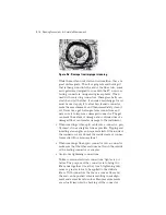
shows the end of a clean fiber-optic cable.
The dark circle in the center of the micrograph is the
fiber’s 125
µ
m core and cladding which carries the light.
The surrounding area is the soft nickel-silver ferrule.
shows a dirty fiber end from neglect or per-
haps improper cleaning. Material is smeared and
ground into the end of the fiber causing light scattering
and poor reflection. Not only is the precision polish lost,
but this action can grind off the glass face and destroy
the connector.
shows physical damage to the glass fiber end
caused by either repeated connections made without
removing loose particles or using improper cleaning
tools. When severe, the damage on one connector end
can be transferred to another good connector that
comes in contact with it.
Summary of Contents for 86121A
Page 2: ...User s Guide Agilent 86121A WDM Channel Analyzer ...
Page 7: ......
Page 10: ...Chapter 1 Getting Started ...
Page 21: ......
Page 24: ...Agilent 86121A Front and Rear Panels 2 3 Agilent 86121A Front and Rear Panels ...
Page 25: ...2 4 Agilent 86121A Front and Rear Panels ...
Page 27: ...2 6 WDM Channel Analyzer Display The S N with Averaging display ...
Page 32: ...The Softkeys 2 11 The Setup menu ...
Page 33: ...2 12 The Softkeys The Disk menu The Printer menu ...
Page 35: ...2 14 Changing the Printer Paper Changing the Printer Paper ...
Page 37: ......
Page 191: ......
Page 205: ...7 14 Regulatory Information Declaration of Conformity ...
Page 239: ......

