background image

General Safety Considerations

Setting Up the 86122A

Agilent 86122A


Multi-Wavelength Meter

, Second Edition

25

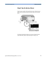
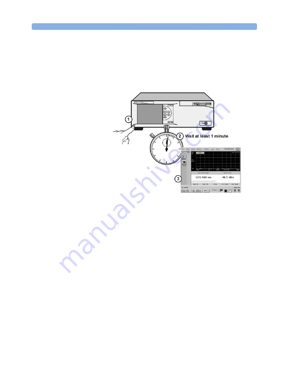
Step 6. Turn On the Line Power

Press the power switch at the lower left-hand corner of the front panel. 
After at least one minute, the display will look similar to the following 
figure.

The Agilent Variable Optical Attenuator modules and Agilent Variable 
Optical Attenuator modules with Power Control is ready to use!

Summary of Contents for 86122A

Page 1: ...Agilent Technologies Agilent 86122A Multi Wavelength Meter User s Guide ...

Page 2: ...preparation or maintenance No other warranty is expressed or implied Agilent Technologies specifically disclaims the implied warranties of Merchantability and Fitness for a Particular Purpose Exclusive Remedies The remedies provided herein are Buyer s sole and exclusive remedies Agilent Technologies shall not be liable for any direct indirect special incidental or consequential damages whether bas...

Page 3: ...instrument Insert the power cable plug only into a socket outlet provided with a protective earth contact Do not negate this protective action by the using an extension cord without a protective conductor WARNING Never look directly into the end of a fiber or a connector unless you are absolutely certain that there is no signal in the fiber ...

Page 4: ...ve You can also contact one of the following centers and ask for a test and measurement sales representative United States 1 800 829 4444 1 800 829 4433 FAX Canada 1 877 894 4414 1888 900 8921 FAX Europe 31 20 547 2111 31 20 547 2190 FAX Japan 0120 421 345 0120 421 678 FAX Mexico 52 55 5081 9469 52 55 5081 9467 FAX Australia 1 800 629 485 1 800 142 134 FAX Asia Pacific 800 930 871 800 908 476 FAX ...

Page 5: ...Step 7 Calibrate the Touch Screen Optional 27 Step 8 Set the Time and Date 29 Step 9 Set the System Standby Mode 30 Step 10 Add a Printer 32 Step 11 Avoid costly repairs 36 Step 12 For More Information 37 Cleaning Connections for Accurate Measurements 38 Choosing the Right Connector 38 Inspecting Connectors 41 Cleaning Connectors 45 Returning the Instrument for Service 49 Preparing the instrument ...

Page 6: ...s 76 Step 1 Consider Measurement Limitations 76 Step 2 Select Basic Measurement Setup Parameters 78 Step 3 Define Laser Line Peaks 81 Step 4 Make Measurements 83 Step 5 Adjust the Graph to Your Preference 86 Step 6 Save Measurement Results 89 Using the Built In Information System 93 Introduction 94 The 86122A Help Contents 95 Description of the Contents Topics 96 Getting Help While Changing Instru...

Page 7: ...Agilent 86122A Multi Wavelength Meter Second Edition 7 Compliance with German Noise Requirements 108 Compliance with Canadian EMC Requirements 108 Declaration of Conformity 109 ...

Page 8: ...8 Agilent 86122A Multi Wavelength Meter Second Edition ...

Page 9: ...tep 8 Set the Time and Date 29 Step 9 Set the System Standby Mode 30 Step 10 Add a Printer 32 Step 11 Avoid costly repairs 36 Step 12 For More Information 37 Cleaning Connections for Accurate Measurements 38 Returning the Instrument for Service 49 Agilent Technologies Service Offices 52 Hard Drive Backup and Recovery 53 This chapter shows you how to properly set up your 86122A Follow the setup ste...

Page 10: ...fe operation and to maintain the product in a safe condition Safety Symbols The caution sign denotes a hazard It calls attention to a procedure which if not correctly performed or adhered to could result in damage to or destruction of the product Do not proceed beyond a caution sign until the indicated conditions are fully understood and met CAUTION The warning sign denotes a hazard It calls atten...

Page 11: ...he AC symbol is used to indicate the required nature of the line module input power The ON symbols are used to mark the positions of the instrument power line switch The OFF symbols are used to mark the positions of the instrument power line switch The CE mark is a registered trademark of the European Community The CSA mark is a registered trademark of the Canadian Standards Association The C Tick...

Page 12: ... outside of the instrument is likely to make the instrument dangerous Intentional interruption is prohibited To prevent electrical shock disconnect the instrument from mains before cleaning Use a dry cloth or one slightly dampened with water to clean the external case parts Do not attempt to clean internally This product complies with Overvoltage Category II and Pollution Degree 2 Always use the t...

Page 13: ...TION REQUIREMENTS When installing the product in a cabinet the convection into and out of the product must not be restricted The ambient temperature outside the cabinet must be less than the maximum operating temperature of the product by 4 C for every 100 watts dissipated in the cabinet If the total power dissipated in the cabinet is greater than 800 watts then forced convection must be used Inst...

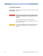
Page 14: ...uivalent device is attached to the optical output connector Refer to the Tunable Laser Modules User s Guide for complete laser safety information NOTE Do NOT under any circumstances look into the optical output or any fiber device attached to the TLS output while the laser is in operation WARNING Use of controls or adjustments or performance of procedures other than those specified herein can resu...

Page 15: ...thing is missing or defective contact your nearest Agilent Technologies Service Office Refer to Agilent Technologies Service Offices on page 52 If the shipment was damaged contact the carrier then contact the nearest Agilent Sales Office Keep the shipping materials for the carrier s inspection The Agilent Sales Office will arrange for repair or replacement at Agilent s option without waiting for c...

Page 16: ... Standard Accessories Accessory Part Number Stylus 1535 5213 Recovery Disk 5011 1306 Getting Started this book 86122 90001 Power Cord depends on country FC PC Connector 08154 61702 Table 2 Instrument Options Option Description Optical Connectors 86122A 021 Straight non angled Contact Interface PC default 86122A 022 Angled Contact Interface APC 86122A 400 Front Panel Fiber Input default 86122A 401 ...

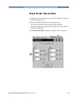
Page 17: ...ations Setting Up the 86122A Agilent 86122A Multi Wavelength Meter Second Edition 17 Table 3 Fiber Optic Adapters Front Panel Fiber Optic Adapter Description Agilent Part Number FC PC 81000FI SC 81000KI DIN 81000SI ST 81000VI ...

Page 18: ...operating 40 C to 70 C Humidity Operating 75 relative humidity at 35 C 5 day soak 95 relative humidity at 40 C 5 day soak for Option 001 Non operating Noncondensing 95 relative humidity at 40 C for 5 day cycle Altitude Operating Up to 2000m 6600 ft Humidity is type tested Type tested means tested but not warranted for continuous operation NOTE Shock 120 g half sine 2 ms pulse Shock is type tested ...

Page 19: ...Up the 86122A Agilent 86122A Multi Wavelength Meter Second Edition 19 Power Requirements Voltage 100 240 V Frequency 50 60 Hz Maximum Power 150 W Weight 14 5 kg 32 lb Dimensions Height 138 mm 5 2 in Width 425 mm 16 7 in Depth 520 mm 20 5 in ...

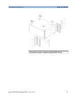
Page 20: ... screws per side 4 Remove feet before rack mounting You must have a rack mount kit to continue with this procedure Refer to Accessories on page 16 NOTE If any items are damaged or missing from the kit contact the nearest Agilent Technologies sales or service office to order a replacement kit Items within the kit are not individually available Table 4 Qty Description 2 Rack Mount Flange 6 Screws 4 ...

Page 21: ...General Safety Considerations Setting Up the 86122A Agilent 86122A Multi Wavelength Meter Second Edition 21 Front Handle Assembly are included with Option 86122A 1CP only ...

Page 22: ...Optional You may connect a standard PC compatible mouse and keyboard to the instrument Refer to the figure below for PS 2 connections You can also use the USB port for a USB keyboard and mouse A keyboard and mouse are not supplied with the 86122A NOTE Do not stack other objects on the keyboard this will cause self test failures at power on NOTE ...

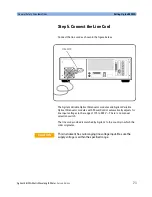
Page 23: ...Optical Attenuator modules and Agilent Variable Optical Attenuator modules with Power Control automatically adjusts for line input voltages in the range of 115 to 240 V There is no manual selection switch The line cord provided is matched by Agilent to the country in which the order originates This instrument has autoranging line voltage input Be sure the supply voltage is within the specified ran...

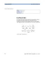
Page 24: ...ndards this instrument has a three wire power cable When connected to an appropriate AC power receptacle this cable earths the instrument cabinet The type of power cable shipped with each instrument depends on the country of destination Line Power Cables Plug Identification Table 5 Line Power Requirements Voltage 110 240 V Frequency 50 60 Hz Maximum Power 150 W ...

Page 25: ...tep 6 Turn On the Line Power Press the power switch at the lower left hand corner of the front panel After at least one minute the display will look similar to the following figure The Agilent Variable Optical Attenuator modules and Agilent Variable Optical Attenuator modules with Power Control is ready to use ...

Page 26: ...e supplied stylus You can also operate the instrument by using an optional mouse For simplicity the term click is used throughout this book to represent clicking or touching an element on the display When you see the term click please remember that you can always touch with your finger or stylus instead The display will always function as a touch screen even when a mouse and keyboard are connected...

Page 27: ...ibration ensures that the touch screen is both accurately aligned and orientated with the display Therefore when you touch an element on the display screen the instrument can detect the task you want to perform 1 On the Utility menu click Touch Screen Calibration The touch screen calibration utility opens The touch screen calibration rarely needs to be performed NOTE ...

Page 28: ... the touch screen configuration utility closes The calibration will time out within 10 seconds if you do not touch the center of the X You can also press Esc on an optional keyboard to exit the touch screen calibration If you miss the center of the X by a significant amount the instrument will display an error message and revert back to the previous calibration This will prevent the touch screen f...

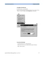
Page 29: ...hown near the top of the display The Set Time and Date dialog box opens 2 Enter the current time and date in one of the following ways Click the time and date text boxes and enter the desired number Click the up or down arrows next to the time and date text boxes until the de sired number is displayed 3 Click Set Time Date Now to apply the changes and close the dialog box ...

Page 30: ...f the instrument is in Continuous sweep mode the motor movement and any related data collection will be suspended Any subsequent activity front panel or remote will reactivate the instrument and return it to it s previous state Using this feature can help extend the life of your instrument To extend the life of the reference laser you should turn off the instrument during long periods of inactivit...

Page 31: ... the Setup menu click Preferences 2 Select a time out period from the System Standby list You can choose 15 min 30 min 1 hr 4 hrs or Never Selecting Never disables this feature To reactivate the display Touch the display screen or a front panel button Move the mouse or press a key on the external keyboard if attached Send a remote command ...

Page 32: ...ion Step 10 Add a Printer Use of a printer with the 86122A is optional Follow the steps below to add a printer 1 Turn off the instrument and connect your printer to rear panel parallel port as shown below 2 Turn on the instrument The 86122A only supports parallel printers USB printers cannot be used NOTE ...

Page 33: ...Enter the protected functions password exit to windows and click Activate If your printer includes an executable file please run the setup exe You can then disregard the rest of this procedure NOTE Installation of programs other than drivers necessary for your printer is not recommended or supported Installation of additional software could render the 86122A software inoperable CAUTION ...

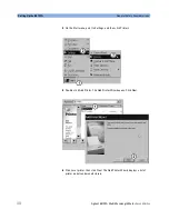
Page 34: ...i Wavelength Meter Second Edition 4 On the Start menu point to Settings and then click Printers 5 Double click Add Printer The Add Printer Wizard opens Click Next 6 Click Local printer then click Next The Add Printer Wizard displays a list of printer models and manufacturers ...

Page 35: ... Deskjet 990c series HP Deskjet 970c series HP Deskjet 950c series HP Deskjet 940c series HP Deskjet 930c series The drivers for the above printers are pre installed for your convenience In the text box of the Install from Disk dialog box type the following path c ossetup PrinterDrivers Or If your printer includes an inf file click Have Disk You can then type the path where the inf file resides 8 ...

Page 36: ...o dirty or damaged cables and accessories When you use improper cleaning and handling techniques you risk expensive instrument repairs damaged cables and compromised measurements Before you connect any fiber optic cable to the Agilent Variable Optical Attenuator modules and Agilent Variable Optical Attenuator modules with Power Control refer to Cleaning Connections for Accurate Measurements on pag...

Page 37: ... are several ways to learn more about your 86122A Continue reading this book Chapter 3 Using the 86122A will help you get started using this instrument Refer to the Help The Help contains the information that would normally be in the user s and programmer s guide Visit our website at http www agilent com Use the keyword 86122A in your search ...

Page 38: ...ectors also vary in the polish curve and concentricity of the core within the cladding Mating one style of cable to another requires an adapter Agilent Technologies offers adapters for most instruments to allow testing with many different cables Figure 1 on page 39 shows the basic components of a typical connector The system tolerance for reflection and insertion loss must be known when selecting ...

Page 39: ...require tighter tolerances than most connectors including the FC PC style can deliver These instruments cannot tolerate connectors with the large non concentricities of the fiber common with ceramic style ferrules When tighter alignment is required Agilent Technologies instruments typically use a connector such as the Diamond HMS 10 which has concentric tolerances within a few tenths of a micron A...

Page 40: ...ocess plus the keyed axis allows very precise core to core alignments This connector is found on most Agilent Technologies optical instruments The soft core while allowing precise centering is also the chief liability of the connector The soft material is easily damaged Care must be taken to minimize excessive scratching and wear While minor wear is not a problem if the glass face is not affected ...

Page 41: ...e or the end of the fiber any stray particles or finger oil can have a significant effect on connector performance Figure 4 shows the end of a clean fiber optic cable The dark circle in the center of the micrograph is the fiber s 125 mm core and cladding which carries the light The surrounding area is the soft nickel silver ferrule Figure 5 shows a dirty fiber end from neglect or perhaps improper ...

Page 42: ...the damage on one connector end can be transferred to another good connector that comes in contact with it The cure for these problems is disciplined connector care as described in the following list and in Cleaning Connectors on page 45 Figure 4 Clean problem free fiber end and ferrule Figure 5 Dirty fiber end and ferrule from poor cleaning Figure 6 Damage from improper cleaning Use the following...

Page 43: ...into a connector make sure that the fib er end does not touch the outside of the mating connector or adapter Avoid over tightening connections Unlike common electrical connections tighter is not better The purpose of the connector is to bring two fiber ends together Once they touch tightening only causes a greater force to be applied to the delicate fibers With connectors that have a convex fiber ...

Page 44: ...ill provide a good low level return loss connection If you test your cables and accessories for insertion loss and return loss upon receipt and retain the measured data for comparison you will be able to tell in the future if any degradation has occurred Typical values are less than 0 5 dB of loss and sometimes as little as 0 1 dB of loss with high performance connectors Return loss is a measure o...

Page 45: ...the end of the fiber during insertion of the cable a second cleaning should be performed It is not uncommon for a cable or connector to require more than one cleaning Agilent Technologies strongly recommends that index matching compounds not be applied to their instruments and accessories Some compounds such as gels may be difficult to remove and can contain damaging particulates If you think the ...

Page 46: ...iately dry the fiber end with a clean dry lint free cotton swab or lens paper 6 Blow across the connector end face from a distance of 6 to 8 inches using filtered dry compressed air Aim the compressed air at a shallow angle to the fiber end face Nitrogen gas or compressed dust remover can also be used Table 7 Dust Caps Provided with Lightwave Instruments Item Agilent Part Number Laser shutter cap ...

Page 47: ...aning seems poor try cleaning the connector again Often a second cleaning will restore proper performance The second cleaning should be more arduous with a scrubbing action Always remove both ends of fiber optic cables from any instrument system or device before visually inspecting the fiber ends Disable all optical sources before disconnecting fiber optic cables Failure to do so may result in per...

Page 48: ...tton fibers remain after cleaning The foam swabs listed in this section s introduction are small enough to fit into adapters Although foam swabs can leave filmy deposits these deposits are very thin and the risk of other contamination buildup on the inside of adapters greatly outweighs the risk of contamination by foam swabs 2 Clean the adapter with the foam swab 3 Dry the inside of the adapter wi...

Page 49: ...an Agilent maintenance plan Agilent will notify you of the cost of the repair after examining the unit When an instrument is returned to a Agilent service office for servicing it must be adequately packaged and have a complete description of the failure symptoms attached When describing the failure please be as specific as possible about the nature of the problem Include copies of additional failu...

Page 50: ...eturned with instrument The original cal data disks 2 Cover all front or rear panel connectors that were originally covered when you first received the instrument 3 Pack the instrument in the original shipping containers Original materials are available through any Agilent office Or use the following guidelines Wrap the instrument in antistatic plastic to reduce the possibility of damage caused by...

Page 51: ...al to protect the instrument and prevent it from moving in the carton If packing foam is not available the best alternative is S D 240 Air Cap from Sealed Air Corporation Commerce California 90001 Air Cap looks like a plastic sheet filled with air bubbles Use the pink antistatic Air Cap to reduce static elec tricity Wrapping the instrument several times in this material will protect the in strumen...

Page 52: ... Center For technical assistance you can contact your local Agilent Call Center Visit http www agilent com and click Contact Us Also see Agilent Technologies Sales and Service Offices on page iv Service Center Before returning an instrument for service you must first call the Agilent Technologies Instrument Support Center In all regions call 1 800 829 4444 ...

Page 53: ...service engineer Create User Backup Image This process creates a backup image of your system This process should be done if you have modified the network parameters and or drivers or if you have updated the system software Recover User Backup Image This process restores your system to the user created backup image A recovery should be done if MS Windows is corrupted or if you have been instructed ...

Page 54: ...tility disk 1 On the Utilities menu click Protected Functions 2 Enter the protected functions password exit to windows and click Activate 3 On the Start menu point to 86122A Tools and then click Create Recovery Disk 4 Insert a floppy disk click OK and then click Create Floppy 5 Toreturn tothe 86122A software cycle the instrument power or click Start point to Programs and then click 86122A ...

Page 55: ...d on established ergonomic principles Improper and prolonged use of keyboards and input devices are among those tasks that have been associated with repetitive strain injury RSI to soft tissues in the hands and arms If you experience discomfort or pain while using your Agilent Technologies product discontinue use immediately and consult your physician as soon as possible Please study the recommend...

Page 56: ... the body such as muscles nerves or tendons become irritated or inflamed RSI has been a reported problem for those who perform repetitive tasks such as assembly line work meatpacking sewing playing musical instruments and computer work RSI has also been observed in those who frequently engage in activities such as carpentry knitting housework gardening tennis windsurfing and lifting children What ...

Page 57: ...ilent 86122A Multi Wavelength Meter Second Edition 57 What if I experience discomfort If you are experiencing any discomfort seek professional medical advice immediately Typically the earlier a problem is diagnosed and treated the easier it is to resolve ...

Page 58: ...om your fingers to activate the buttons or scroll wheel on your mouse scrolling mouse trackball or other input device Using too much force can place unnecessary stress on the tendonsand muscles in your hands wrists and forearms If you are using a scrolling mouse be sure to keep your fingers and hand in a relaxed neutral position when activating the scroll wheel Also this type of mouse features sof...

Page 59: ... 64 Main Screen Layout 66 Graphs and Tables 68 Front Panel Buttons 69 Menus 71 86122A Dialog Box Operation 75 Making Measurements 76 Step 1 Consider Measurement Limitations 76 Step 2 Select Basic Measurement Setup Parameters 78 Step 3 Define Laser Line Peaks 81 Step 4 Make Measurements 83 Step 5 Adjust the Graph to Your Preference 86 Step 6 Save Measurement Results 89 ...

Page 60: ...velength division multiplexed DWDM systems and the multiple lines of Fabry Perot lasers With the 86122A you can quickly and easily measure the following parameters Up to 1000 laser lines simultaneously Wavelengths and powers Average wavelength Total optical power Laser line separation Laser drift wavelength and power Optical signal to noise ratios Fabry Perot lasers This chapter gives you an overv...

Page 61: ...avelength Meter Second Edition 61 Differences Between the 86122A and the 86120C The 86122A is backward compatible with the 86120C However because of improvements in the 86122A there are some operational differences from the 86120C For your convenience these differences are listed below ...

Page 62: ... remains for back ward compatibility but has no affect on the 86122A Data logging This new feature of the 86122A allowsyou torecord measurement data over time for later analysis Drift Application This application has been enhanced for the 86122A Dropped added channels If the number of channels changed during a drift measurement the 86120C would stop the measurement and generate an error The 86122A...

Page 63: ... this command query returned the setting to be used for the default FETCH or READ commands For the 86122A this command query re turns the current configuration of the instrument SYST VERS This query returns the SCPI compliance version The 86120C ver sion was 1995 0 The 86122A version is 1999 0 DISP UNIT WAV This new command allows you to set the wavelength unit of the display DISP WIND2 The new co...

Page 64: ...ne 2 Mouse PS 2 for optional mouse 3 Keyboard PS 2 for optional keyboard 4 Printer Parallel printer port 5 USB For a USB keyboard and mouse USB printers are not supported 6 LAN A keyboard must be used to set up LAN connectivity 7 GPIB Fully programmable complies with IEEE 488 2 8 Video Output SVGA An optional rear panel optical input is also available NOTE ...

Page 65: ...Panel Features Using the 86122A Agilent 86122A Multi Wavelength Meter Second Edition 65 Front Panel 1 Line button 2 Display screen 3 Front panel buttons 4 3 5 inch disk drive 5 Optical Input 9 125 mm single mode fiber ...

Page 66: ...ccess measurement setup data view and application functions There is a dedicated toolbar for each function To open the desired toolbar press the front panel button that corresponds with the functions you want to perform 2 Wavelength Limiting Status Displays the wavelength limiting state 3 Peak Criteria Button Click this button to access the peak criteria settings and change the definition of peak ...

Page 67: ...gation of the instrument You can also use a mouse The graphical display shows the transformed uncorrected frequency domain measurement data in a spectrum analyzer type graph 12 Front Panel Buttons The 10 front panel buttons can be accessed with your finger or a stylus 13 Touch Screen Enable Disable Button Click or touch this button to disable the pointing devices touch screen and mouse The indicat...

Page 68: ...or peak wavelengths C The trace marker allows you to find the approximate wavelength of any point on the measurement trace An area in the upper right corner of the graph displays the approximate trace marker wavelength but not power D The horizontal green line represents the peak threshold one of two criteria used to define peak wavelengths For more information refer to Peak Criteria E The peak ma...

Page 69: ...ssed with your finger or a stylus These are referred to as the front panel buttons This section explains the function of each front panel button Press this button to return control of the instrument to the front panel The Local and AC power buttons are the only front panel controls active when the instrument is in remote operation Press this button to return the instrument to its factory default c...

Page 70: ... variety of measurement and display setup functions Press this button to open the Data View toolbar You can then configure the tabular display as desired Press this button to open the Applications toolbar You can then select your desired measurement application Press this button to place the instrument in single sweep mode and initiate a single sweep of the instrument Press this button to place th...

Page 71: ...t 86122A Multi Wavelength Meter Second Edition 71 Menus The instrument menus provide access to all functions This section shows the layout of each menu For detailed information on each of these menus refer to the Help The File menu ...

Page 72: ...Using the 86122A Menus 72 Agilent 86122A Multi Wavelength Meter Second Edition The View menu The Setup menu ...

Page 73: ...Menus Using the 86122A Agilent 86122A Multi Wavelength Meter Second Edition 73 The Measure menu The Utilities menu The Apps menu ...

Page 74: ...Using the 86122A Menus 74 Agilent 86122A Multi Wavelength Meter Second Edition The Help menu ...

Page 75: ...Wavelength Meter Second Edition 75 86122A Dialog Box Operation The 86122A dialog boxes allow real time changes to instrument settings Because of this the dialog boxes do not have OK Apply and Cancel buttons When you have finished changing a setting simply click Close ...

Page 76: ...nsider Measurement Limitations Before connecting a signal and making a measurement please consider the following measurement limitations The front panel OPTICAL INPUT connector uses a single mode input fiber NOTE 10 dBm is the maximum total displayed input power Do not exceed 18 dBm source power The Agilent 86122A s input circuitry can be damaged when total input power exceeds this level CAUTION ...

Page 77: ... compromised measurements Before you connect any fiber optic cable to the Agilent Variable Optical Attenuator modules and Agilent Variable Optical Attenuator modules with Power Control refer to Cleaning Connections for Accurate Measurements on page 38 CAUTION Always remove both ends of fiber optic cables from any instrument system or device before visually inspecting the fiber ends Disable all opt...

Page 78: ...gth range Laser line widths are assumed to be less than 2 5 GHz Step 2 Select Basic Measurement Setup Parameters Basic measurement setup parameters that you should choose before making a measurement are medium device type units and sweep mode Select the Medium The 86122A can display wavelength values in a vacuum or in standard air 1 Press and click 2 Click the Medium tab and select In Air or In Va...

Page 79: ... and select the wavelength and amplitude units 3 Click Close Select the Device Type You can optimize or match the measurement technique of the 86122A to the type of device you are measuring narrowband or broadband Narrowband devices include DFB lasers and modes of Fabry Perot lasers Broadband devices include LEDs optical filters and chirped lasers 1 Press and click 2 Click the Device Type tab and ...

Page 80: ...tic for saving results or printing Press to continuously measure the input spectrum In this mode a measurement sweeps occurs approximately every 0 5 seconds This is useful if you want the data to be continuously updated You can also set up data logging to perform measurement sweeps at any desired interval The green SWP indicator in the lower right hand corner is lit when a measurement is being acq...

Page 81: ...than or equal to the peak excursion In addition peaks are only measured within the wavelength limits that you specify In this figure only three laser lines are identified as peaks responses 1 3 and 4 Response 2 is not identified as a peak because it is below the peak threshold Responses 4 and 5 are identified as one peak laser line This is because the min imum point between 4 and 5 does not drop t...

Page 82: ...n box and enter the excursion value 6 Click Close Use Wavelength Limiting to Define Peaks 1 Press and click 2 Click the Wavelength Limiting tab 3 Select On 4 Click the Limit Start Wavelength box and enter the start wavelength value 5 Click the Limit Stop Wavelength box and enter the stop wavelength value 6 Click Close ...

Page 83: ...avelength Meter Second Edition 83 Step 4 Make Measurements The 86122A can make a wide variety of wavelength and power measurements Peak Wavelength and Power Press and click Multiple Laser Lines Press and click Average Wavelength and Total Power Press and click ...

Page 84: ...read the relative wavelength values in the Delta WL column Laser Channel Flatness You can use relative power measurements to measure flatness pre emphasis in a WDM system Simply select one carrier as the reference and measure the remaining carriers relative to the reference level The power differences represent the system flatness 1 Press and click 2 Select the channel with the largest amplitude a...

Page 85: ...rge signal levels are present By entering a power offset equal to the amount of attenuation at the instrument s input accurate amplitude measurements are shown on the display 1 Connect an optical attenuator between the front panel OPTICAL INPUT connector and the fiber optic cable from your device The attenuator must reduce the total input power to the Agilent 86122A so that it is below 10 dBm 2 Pr...

Page 86: ... After you have set up your measurement you may wish to adjust the graph x axis or move markers Adjust the X Axis You can adjust the x axis in any of the following ways Click and enter graph limits as start stop or center span Select an x axis control from theGraph Control list Click anywhere on the graph and drag to the left or right ...

Page 87: ...ing ways Click any cell in the Peak column of the table The peak marker will move to the corresponding peak wavelength in the graph If ClickZoom is enabled click any cell in the Wavelength column of the table The peak marker will move the corresponding peak wavelength in the graph and the graph will zoom in to that peak To zoom out click the Wavelength cell again ...

Page 88: ...88 Agilent 86122A Multi Wavelength Meter Second Edition Select Peak Marker from the Graph Control list Click close to a peak on the graph SelectPeak Marker from theGraph Controllist Click anywhere on the graph and drag to the left or right ...

Page 89: ... the following ways Select Trace Marker from the Graph Control list Click any point on the graph Select Trace Marker from the Graph Control list Click anywhere on the graph and drag to the left or right Step 6 Save Measurement Results After you have set up your measurement and the graphical display you may wish to save measurement results Save Data Press to open the Save Meas Data dialog box Selec...

Page 90: ...to Save and then click Save Screen Image Select a file name and click Save Data Logging Data logging allows you to record measurement data over time for later analysis Follow the steps below to set up data logging 1 On the Measure menu click Data Logging 2 Enter the Logging Duration and Logging Interval time 3 Click Start Data Logging ...

Page 91: ...lowing example applications To log data for a long term stability drift test set the data logging duration to 24 hrs and the interval to 5 minutes To log data for a turn on transient test to observe how lasers change during warm up set the data logging duration to 5 minutes and the interval to 0 time free run ...

Page 92: ...Using the 86122A Making Measurements 92 Agilent 86122A Multi Wavelength Meter Second Edition ...

Page 93: ... Using the Built In Information System Introduction 94 The 86122A Help Contents 95 Description of the Contents Topics 96 Getting Help While Changing Instrument Settings 98 Hiding the Help 99 Printing the Contents of a Topic 100 Selecting the Help Language 101 ...

Page 94: ...mer s guide To access the Help simply click Contents on the Help menu This will display the contents topic that is shown in the figure on the following page Navigating through the Help should be familiar to you because it is similar to other Windows applications You can of course navigate through the help by either using the touch screen or the mouse In this chapter you ll learn features that are ...

Page 95: ...hows the 86122A Help contents This is the starting point for learning how to use your Agilent Variable Optical Attenuator modules and Agilent Variable Optical Attenuator modules with Power Control In addition to the 10 topics presented in the contents be sure to use the index buttons located along the bottom These can be very helpful in locating a topic of interest ...

Page 96: ...ion you may want to read first Graphs Tables and Markers This topic explains how to use graphs tables and markers Applications This topic provides information about the available measurement applications Making Measurements This topics explains the steps required to make a measurement Files Printing and Utilities This topic contains descriptions of all file printing and utility functions Programmi...

Page 97: ...ort This topic provides information about instrument messages and errors and technical support information Description of Functions This topic contains descriptions of all instrument functions Specifications This topic lists specifications and characteristics for the instrument Connectors This topic provides information about optical connector care Table 8 ...

Page 98: ...me and date used by the Agilent Variable Optical Attenuator modules and Agilent Variable Optical Attenuator modules with Power Control When changing the settings as shown in the following figure click the Book icon to learn general information Or click the What s this icon to find more specific information about an item After clicking the What s this icon keep your finger on the display and drag t...

Page 99: ...he Help When using the Help you can temporarily hide it so that you can see the entire display You can then re display the Help with the same topic still showing To hide the Help click the Minimize button located at the top of the Help win dow To re display the Help click the Restore button that is shown on the display ...

Page 100: ...ic by clicking the Print button located at the top of the Help window You can print the entire contents of a pop up Help window by following the steps below 1 Connect a printer and a mouse pointing device to the Agilent Variable Optical Attenuator modules and Agilent Variable Optical Attenuator modules with Power Control 2 Place the pointer over the topic and click the right button Then click on P...

Page 101: ...vailable in more than one language On the Help menu click Select Help Language and then click the language you want to view Please ensure that the Help file is closed before changing the language selection You can only view one version of help at a time Help Version Refer to the English version of help to view the most current information about instrument features and specifications ...

Page 102: ...Using the Built In Information System Selecting the Help Language 102 Agilent 86122A Multi Wavelength Meter Second Edition ...

Page 103: ... Wavelength Meter Second Edition 103 5 Specifications and Regulatory Information Specifications 104 Compliance with German Noise Requirements 108 Compliance with Canadian EMC Requirements 108 Declaration of Conformity 109 ...

Page 104: ...z For lines separated by less than the specified amount wavelength accuracy is reduced Display Resolution Fast update mode 0 0001 nm N A Units nm vacuum or standard air cm 1 THz Power Calibration Accuracy 0 5 dB at 30 nm from 1310 and 1550 nm Flatness 1 0 2 dB 1270 to 1600 nm 0 5 dB 1270 to 1650 nm 30 nm from any wavelength Linearity 0 3 dB 1270 to 1600 nm Lines above 30 dBm Polarization Dependenc...

Page 105: ...22A Delta Modes Delta wavelength delta power delta wavelength and power Built in Automatic Measurement Applications Signal to Noise Ratio 1 4 Channel Spacing 100 GHz Channel Spacing 50 GHz 35 dB with 100 averages 27 dB with 100 averages 0 1 nm noise bandwidth Lines above 25 dBm Drift Maximum minimum total drift max min of wavelengths and powers over time Fabry Perot Characterization Mean wavelengt...

Page 106: ... 5 2 in x 16 7 in x 20 5 in 14 5 kg 32 lb Environmental Operational Temperature Humidity 3 15 C to 35 C 75 R H at 35 C Shock 3 120 g Half sine 2 msec pulse Vibration 3 2 g rms 0 5 g 0 to peak Random 5 to 500 Hz 10 min axis Sine 5 to 500 Hz 1 octave min EMC Conducted and radiated interference is in compliance with CISPR Pub 11 IEC 801 2 IEC 801 3 IEC 801 4 and IEC 555 2 Storage Temperature Humidity...

Page 107: ...er attached to the optical output connector Pressing the acitve button enables the laser The laser is on when the green LED is lit The use of optical instruments with this product will increase eye hazard Refer servicing only to qualified and authorized personnel Table 10 Laser type LED Wavelength 1270 1650 nm Max CW output power 1 nW Beam waist diameter 10 µm Numerical aperture 0 1 Laser class ac...

Page 108: ...ation on Noise Declaration for Machines Laermangabe nach der Maschinenlaermrerordnung 3 GSGV Deutschland Compliance with Canadian EMC Requirements This ISM device complies with Canadian ICES 001 Cet appareil ISM est conforme a la norme NMB 001 du Canada Table 11 Notice for Germany Noise Declaration Acoustic Noise Emission Geraeuschemission LpA 70 dB LpA 70 dB Operator position am Arbeitsplatz Norm...

Page 109: ...Declaration of Conformity Specifications and Regulatory Information Agilent 86122A Multi Wavelength Meter Second Edition 109 Declaration of Conformity ...

Page 110: ...Specifications and Regulatory Information Declaration of Conformity 110 Agilent 86122A Multi Wavelength Meter Second Edition ...

Page 111: ......

Page 112: ...Agilent Technologies GmbH 2004 Printed in Germany November 2004 Second edition November 2004 86122 90004 www agilent com Agilent Technologies ...

Reviews: