background image

5-13

Status Listings

SCPI-Defined Errors

Device-specific errors

An <error/event number> in the range [–399, –300] or [1, 32767] indicates the instrument has 
detected an error which is not a command error, a query error, or an execution error; some 
device operations did not properly complete, possibly due to an abnormal hardware or firmware 
condition. These codes are also used for self-test response errors. The occurrence of any error in 
this class should cause the device-specific error bit (bit 3) in the event status register (IEEE 488.2, 
section 11.5.1) to be set. The meaning of positive error codes is device-dependent and may be 
enumerated or bit mapped; the <error message> string for positive error codes is not defined by 
SCPI and available to the device designer. Note that the string is not optional; if the designer 
does not wish to implement a string for a particular error, the null string should be sent (for exam-
ple, 42,””). The occurrence of any error in this class should cause the device-specific error bit (bit 
3) in the event status register (IEEE 488.2, section 11.5.1) to be set. Events that generate device-
specific errors shall not generate command errors, execution errors, or query errors; see the other 
error definitions in this section. 

–277 

desc = “Macro redefinition not allowed” 
help = ““
[Indicates that a syntactically legal macro label in the *DMC command could not be 
executed because the macro label was already defined (see IEEE 488.2, 10.7.6.4).]

–278 

desc = “Macro header not found” 
help = ““
[Indicates that a syntactically legal macro label in the *GMC? query could not be 
executed because the header was not previously defined.] 

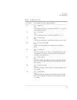
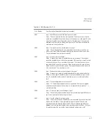
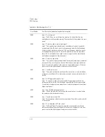
Table 5-2. Execution Errors (3 of 3)

Error Number

Error Description [description/explanation/examples] 

Summary of Contents for 8614 B Series

Page 1: ...Agilent 8614xB Series Optical Spectrum Analyzer User s Guide ...

Page 2: ...other country Agilent warrants that its software and firmware designated by Agilent for use with an instrument will execute its programming instructions when properly installed on that instrument Agilent does not warrant that the operation of the instrument software or firmware will be uninter rupted or error free Limitation of Warranty The foregoing warranty shall not apply to defects resulting f...

Page 3: ...cate the required nature of the line module input power The ON symbols are used to mark the positions of the instrument power line switch The OFF symbols are used to mark the positions of the instrument power line switch The CE mark is a registered trademark of the European Community The CSA mark is a registered trademark of the Canadian Standards Association The C Tick mark is a registered tradem...

Page 4: ... supplied in a safe condition The documenta tion contains information and warnings that must be followed by the user to ensure safe operation and to maintain the product in a safe condition Install the instrument according to the enclosure protection provided This instrument does not protect against the ingress of water This instrument protects against finger access to hazardous parts within the e...

Page 5: ... INPUT connector is no exception When you use improper cleaning and handling techniques you risk expensive instrument repairs damaged cables and compromised measurements Before you connect any fiber optic cable to the Agilent 8614x series refer to Cleaning Connections for Accurate Measurements on page 6 8 CAUTION This product complies with Overvoltage Category II and Pollution Degree 2 CAUTION Do ...

Page 6: ...ng by not using this cord may cause instrument damage CAUTION Do not connect ac power until you have verified the line voltage is correct as described in Line Power Requirements on page 1 10 Damage to the equipment could result CAUTION This instrument has autoranging line voltage input Be sure the supply voltage is within the specified range CAUTION The Agilent 8614xB contain a light source classi...

Page 7: ...ging Files 2 18 Analyzing Measurement Data 2 26 Analyzer Operating Modes 2 29 3 Function Reference 4 Remote Front Panel Operation Remote Front Panel 4 2 5 Status Listings Overview 5 2 Error Reporting Behavior 5 4 SCPI Defined Errors 5 5 OSA Notices 5 16 OSA Warnings 5 17 Application Specific Warnings 5 29 OSA Status Errors 5 35 OSA Errors 5 36 Firmware Errors 5 38 6 Maintenance Changing the Printe...

Page 8: ...Contents 2 Contents 7 Specifications and Regulatory Information Definition of Terms 7 3 Specifications 7 5 Regulatory Information 7 19 Declaration of Conformity 7 20 ...

Page 9: ...1 Product Overview 1 2 Setting Up the Analyzer 1 8 Making a Measurement 1 12 The Menu Bar 1 15 The Softkey Panels 1 16 Laser Safety Information 1 26 Product Options and Accessories 1 27 Getting Started ...

Page 10: ...hannel dropping For Agilent 86146B instruments this mode also allows the ability to measure time resolve chirp TRC Built in Applications Built in applications allow fast repeatable measurements for WDM systems lasers amplifiers and passive components These applications can be added through a firmware upgrade WDM Application This application allows you to measure DWDM sub system components such as ...

Page 11: ... Getting Started Product Overview Amplifier Test Application This application simplifies the process of characterizing gain and noise figure of optical amplifiers such as EDFA s SOA s and Raman amplifiers ...

Page 12: ...1 4 Getting Started Product Overview Agilent 8614xB Front and Rear Panels ...

Page 13: ...1 5 Getting Started Product Overview ...

Page 14: ...1 6 Getting Started Product Overview Optical Spectrum Analyzer Display Figure 1 1 Optical Spectrum Analyzer Display ...

Page 15: ...1 7 Getting Started Product Overview Figure 1 2 Display Annotations ...

Page 16: ...1 8 Getting Started Setting Up the Analyzer Setting Up the Analyzer Step 1 Receive and Inspect the Shipment ...

Page 17: ...ier then contact the nearest Agilent Technologies Sales Office Keep the shipping materi als for the carrier s inspection The Agilent Technologies Sales Office will arrange for repair or replacement at Agilent Technologies option without waiting for claim settlement Step 2 Connect Accessories and Power Cord Although you can operate all instrument functions using only the front panel keys and track ...

Page 18: ...the instrument s rear panel Parallel connector Use a parallel Centronics printer cable such as an HP C2950A 2 m or HP C2951A 3 m r The line cord provided is matched by Agilent Technologies to the country of origin on the order Refer to Accessories on page 1 28 1 HP and Hewlett Packard are U S registered trademarks of Hewlett Packard Company Table 1 2 Line Power Requirements Voltage 100 115 230 240...

Page 19: ... page 6 8 CAUTION A front panel connector saver is provided with Agilent 8614x series instruments Attach the connector saver to the front panel INPUT connector of the instrument You can now make your connections to the connector saver instead of the instrument This will help prevent damage to the front panel INPUT connector of the instrument Damage to the front panel INPUT connector is expensive i...

Page 20: ...o The Menu Bar on page 1 15 and The Softkey Panels on page 1 16 Instrument setup A source signal must be present at the input of the optical spectrum analyzer In this procedure a Fabry Perot laser is used as the source You can use another source or the optional 1310 1550 nm eeled If another source is being used the display will differ from those shown To set the OSA to a known state Press the fron...

Page 21: ...s described in Cleaning Connections for Accurate Measurements on page 6 8 2 Enable the source Press Markers Peak Search to find the peak signal power 3 Press the front panel Auto Align key to optimize the detection of the incoming signal This takes a few moments to complete To perform a peak search 4 Press the front panel Auto Meas key to locate and zoom inon the signal Please waituntil the Auto M...

Page 22: ...ta marker 5 Press the front panel Markers key 6 Press the More Marker Functions softkey 7 Press the Delta Marker softkey to activate the delta marker and the active function area 8 Use the knob step keys or numeric entry pad to move the delta marker 9 The reference marker remains stationary Trace with delta marker Printing the display 10 Press the Print key to print a copy of the display The outpu...

Page 23: ...ptions drop down menus Each menu selection includes a descriptive label Action Indicates the selection will perform an action such as making a measurement or printing the display Panel Indicates the selection will open a softkey panel The File Menu The Measure Menu The Applications Menu The Options Menu ...

Page 24: ...ction includes brief descriptions of the following menus See Chapter 3 Function Reference for addi tional information on each of the OSA functions The Amplitude Menus 1 17 The Applications Menus 1 17 The Bandwidth Sweep Menus 1 19 The Markers Menus 1 20 The Save Recall Menus 1 21 The Systems Menus 1 22 The Traces Menus 1 24 The Wavelength Menus 1 25 ...

Page 25: ... selection on the menu bar The Applications Menus You can access the Applications Appl s softkeys by using the front panel Appl s key or the Applications menu Launch an Installed Application section on the menu bar For a complete description of the applications refer to the Agilent 8614xB Series Measurement Applications User s Guide that came with your instrument ...

Page 26: ...1 18 Getting Started The Softkey Panels ...

Page 27: ...tting Started The Softkey Panels The Bandwidth Sweep Menus You can access the Bandwidth Sweep softkeys by using the front panel Bandwidth Sweep key or the Measure menu Bandwidth Sweep selection on the menu bar ...

Page 28: ...1 20 Getting Started The Softkey Panels The Markers Menus You can access the Markers softkeys by using the front panel Markers key or the Measure menu Markers selection on the menu bar ...

Page 29: ...s The Save Recall Menus You can access the Save Recall softkeys and setup panels by using the drop down File menu Save Recall selection or the front panel Save Recall key Use these functions to save recall and print the measurement results ...

Page 30: ...1 22 Getting Started The Softkey Panels The Systems Menus You can access the System softkeys by using the front panel System key or the Options menu System selection on the menu bar ...

Page 31: ...1 23 Getting Started The Softkey Panels The Systems Menus continued ...

Page 32: ...1 24 Getting Started The Softkey Panels The Traces Menus You can access the Traces softkeys by using the front panel Traces key or the Measure menu Traces selection on the menu bar ...

Page 33: ...1 25 Getting Started The Softkey Panels The Wavelength Menus You can access the Wavelength softkeys by using the front panel Wavelength key or the Mea sure menu Wavelength selection on the menu bar ...

Page 34: ...tion can seriously damage your eyesight Do not enable the laser when there is no fiber attached to the optical output connector The use of optical instruments with this product will increase eye hazard Refer servicing only to qualified and authorized personnel Laser type Edge emitting LED EELED Wavelength 1310nm 1550 nm Max CW output power 50 µW Beam waist diameter 9 µm Numerical aperture 0 1 Lase...

Page 35: ...nalysis Application Passive Component Test Application Amplifier Test Application Source Test Application Alternative Connector Interface FC PC DIN ST SC Opt 001 Opt 002 Opt 004 Opt 005 Opt 006 Opt DPCa Included Included Included Included Standard Opt 013 Opt 014 Opt 017 a Option available for 86146B only Opt 006 Not Applicable Included Included Included Included Standard Opt 013 Opt 014 Opt 017 M...

Page 36: ...ustralia New Zealand China 8120 1369 1 902 Power Cord Europe 8120 1689 1 903 Power Cord United States 8120 1378 1 906 Power Cord Switzerland 8120 2104 1 912 Power Cord Denmark 8120 3997 1 917 Power Cord South Africa India 8120 4211 1 918 Power Cord Japan 8120 4753 1 919 Power Cord Israel 8120 5182 1 920 Power Cord Argentina 8120 6868 1 921 Power Cord Chilean 8120 6979 1 922 Power Cord China 8120 8...

Page 37: ...ht Source Option 004a 1310 1550 EELED Option 005a 1550 EELED Option 006 Calibrator Photo diode Input MonoOutput 1 86143B Opt 025 9 µm 50 µm N A N A N A 9 µm 9 µm N A N A 86145B 9 µm N A N A N A 9 µm N A N A 86142B 9 µm 62 5 µm 9 µm 9 µm 9 µm N A N A 86146B 9 µm 62 5 µm 9 µm 9 µm 9 µm 50 µm 9 µm a Options 002 004 and 005 are exclusive ...

Page 38: ...nector Interfaces See Agilent 81000 series See Agilent 81000 series External 10 dB Attenuator FC PC Opt 030 Opt 030 Rack Mount Flange Kit Opt AX4 N A Transit Case 9211 2657 9211 5604 Soft Carrying Case N A Opt 042 BenchLink Lightwave Softwarea Standard Standard a Agilent N1031A BenchLink Lightwave allows transfer of measurement results over a GPIB Interface to a PC for the purposes of archiving pr...

Page 39: ...s and Accessories Front Panel Fiber Optic Adapters Front Panel Fiber Optic Adapter Description Agilent Part Number FC PCa a The FC PC is the default front panel optical connector 08154 61702 SC 08154 61708 DIN 08154 61703 ST 08154 61704 ...

Page 40: ...1 32 Getting Started Product Options and Accessories ...

Page 41: ...2 Setting Up Measurements 2 2 Calibrating Wavelength Measurements 2 13 Saving Recalling and Managing Files 2 18 Analyzing Measurement Data 2 26 Analyzer Operating Modes 2 29 Using the Instrument ...

Page 42: ...g information that will help you set up a wavelength measure ment Adjusting Setup Conditions Operating the Internal White Light Source Averaging Traces Setting Video Bandwidth Using Span to Zoom In Setting the Sensitivity Triggering a Measurement Moving the Active Function Area Indicating an Update is Needed ...

Page 43: ... to field in the dialog box The highlighted parameter can be changed The front panel number keys step keys and knob allows the user to enter a numeric value in the highlighted field Select selects the highlighted parameter You can enter values for a selected parameter using the front panel knob or numeric entry pad Defaults resets the parameters to their default condition Close Panel saves the cur...

Page 44: ...urce provides the widest wavelength input for stimulus response measurements you can also use an LED or the spontaneous emission from an optical amplifier The displayed response is a convolution of the analyzer s resolution bandwidth and the amplitude response of the device under test Because of this convolution the analyzer s resolution band width affects both dynamic range and the ability to res...

Page 45: ... This would result in a long measure ment time where trace averaging would be faster Refer to Averaging on page 3 13 1 From the front panel press Traces Averaging 2 Toggle to select the Averaging on or off 3 Select from the 10 20 50 or 100 softkeys or use the knob step keys or numeric entry pad to enter the desired average count N o te For measurements with fast polarization scrambling video filte...

Page 46: ...at the end of each trace point interval The filter function is varied with the video bandwidth function from 100 mHz to 3 0 kHz or the bandwidth of the currently selected transimpedance amplifier whichever is less Increased filtering provides greater sensitivity The detection mode is automatically determined by the instrument You can adjust the settings of video bandwidth sensitivity or sweep time...

Page 47: ... polarization scrambling use trace averaging to improve measurement repeatability Trace averaging is faster than video filtering for the slow polarization scrambling application Using Span to Zoom In To see a more detailed view of the device s response decrease the wavelength span to expand the trace This will enable you to precisely focus in on the desired measurement area Refer to Span on page 3...

Page 48: ...ree sweeps in three different gain stages to make the measurement This depends on the settings for sensitivity reference level auto range and also the particular device being measured The final data trace is a blended composite of each trace taken in the different gain stages An increase in sensitivity may also require a narrower video bandwidth which will slow the sweep speed Normally the optical...

Page 49: ...ible signal with a minimum of 0 Vdc and a maxi mum of 5 V Gated triggering ignores the spectrum when the trigger input is low It usually is used in conjunc tion with the Max Hold function during several sweeps Gated triggering is used to select data samples containing valid information When the gating signal is high the data sample is accepted When the gating signal is low the data sample is repla...

Page 50: ...l the gaps because the high and low levels of the gating signal occur independent of the grating position Gated triggering has no time limit for the high or low level It can be used to characterize pulses as narrow as a few microseconds or to obtain a spectrum whose timing exceeds the maximum 6 5 ms delay of the ADC trigger mode 1 On the front panel press Bandwidth Sweep More BW Sweep Functions Tr...

Page 51: ...ght different locations This allows you to place the active area in a location that will not interfere with the trace information Refer to Active Function Area Assist on page 3 2 1 Press the front panel System key 2 Press the Move Active Area softkey Each press of the softkey moves the active function area to one of eight onscreen locations ...

Page 52: ...ator to on start wavelength stop wavelength sensitivity auto manual auto range enable disable sensitivity video bandwidth auto manual resolution bandwidth video bandwidth gated sweep enable disable sweep continuous single sweep time auto manual sweep time sweep trace length reference level dB per division reference level position Y scale linear log mode amplitude correction enable disable current ...

Page 53: ... the 86140X Series Optical Spectrum Analyzers Literature part number 5980 0043E Overview Wavelength calibration routines improve wavelength accuracy by determining errors and cor recting them with offsets using linear interpolation when necessary For maximum wavelength accuracy calibration points spaced a maximum of 10 nm apart are recommended You can perform a wavelength calibration by using one ...

Page 54: ...ration time for an internal calibration but will provide enhanced wavelength accuracy over the full range Manual method using the internal calibrator 1 Access the EWC setup panel System More System Functions Service Menu Adv Service Functions More Adv Service Menu Enhanced Wvl Cal Setup 2 Enable the function if necessary and select the desired calibration range 3 Clean all connectors and connect t...

Page 55: ...method using an external source 1 Connect the external source to the OSA input 2 Auto align the OSA to the input signal 3 Access the Wavelength Calibration setup panel System Calibration Wavelength Cal Setup 4 Select Air or Vacuum reference for the signal source 5 Set the signal source to External 6 Select the desired Calibration Wavelength This wavelength must be within 2 5 nm of the source wavel...

Page 56: ...outlined are those writ ten in the program 1 A signal is sent from a tunable laser source into a multi wavelength meter and the OSA simultaneously 2 The wavelength of the input signal is measured on both instruments 3 The two measured values are compared 4 Taking the multi wavelength meter readings as actual the software calculates the error offsets at each wavelength using the equation WL Error O...

Page 57: ...ents To insure this offset process has provided sufficient accuracy the wavelength readings of the multi wavelength meter and the OSA should be compared to verify the wavelength accuracy and determine if a full multipoint wavelength recalibration is necessary ...

Page 58: ...estoring the Internal Memory Saving Measurement Trace Data Recalling Measurement Trace Data File Sharing and Printing over a Network Adding a Title to the Display Refer to Title Display Setup Panel on page 3 85 and to Date Time Display Setup Panel on page 3 19 1 Press the front panel System key 2 Press the Set Title softkey The Title Setup panel appears The Title Setup panel 3 To view the title on...

Page 59: ...les or catalogs on the floppy disk will be destroyed Any successive backup operations will overwrite the previous backup information so only the latest backup information can be recov ered through the Restore Internal Memory operation Restore Internal Memory The analyzer Restore Utility screen appears This operation will remove all files from internal memory and replace them with files from backup...

Page 60: ...rement data in a binary format dat file This includes the traces and all mea surement conditions The dat file format can only be read by the analyzer You will not be able to view this file on your PC When the file is recalled the instrument state will be set to the same state as when the file was saved Save Trace s Only The Trace s Only files are saved in comma separated variable csv format and ar...

Page 61: ...eadable by many different kinds of software The file is saved with gif extension GIF supports up to 8 bit color 256 colors Save to Allows you to choose between saving data to a floppy disk or to internal memory File Name Selects manual or automatic mode for choosing a file name 4 If you have chosen Auto to select the file name press the Auto Save softkey The analyzer will generate a filename and s...

Page 62: ...ers Select the Clear Line function to delete the entire filename When you finish entering the filename press the SAVE FILE softkey Entering a Filename using an External Keyboard There must be a PS 2 keyboard connected to the analyzer prior to bootup Press TAB on the keyboard to highlight the entry field Enter the filename using the keyboard When you finish entering the filename press the SAVE FILE...

Page 63: ...the measurement state previously saved as FASTSAVE dat by the Fast Meas Save function N o te The auto span value will not be saved with the measurement Recalling Measurement and Trace Data N o te To insure accurate measurements a wavelength calibration should be performed each time measurement data is recalled from memory 1 Press the front panel Save Recall key 2 Press the Recall Menu softkey 3 Th...

Page 64: ... a floppy disk or from internal memory 4 When you are satisfied with your selections press the Choose File to Recall softkey The Catalog setup panel opens The Catalog setup panel 5 Use the arrow keys or Prev File Next File softkeys to highlight the desired file Press RECALL FILE to load the selected file ...

Page 65: ...GPIB Network Setup User Share Identity 3 Enter the User Name Password and Workgroup Use the keyboard to enter the information or press Edit Field to access the User Workgroup Setup panel then close the panel 4 From the Network Setup press File Share and enter the Share Path and optional IP address The format of the share path is server share name Please note that you cannot specify directories wit...

Page 66: ...Menu on page 3 34 Marker Setup on page 3 35 and More Marker Functions on page 3 40 Markers are always placed on the currently selected active trace Therefore use the Active Trace function to activate the desired trace then select an active marker to be placed on that trace When multiple markers are currently used on multiple traces the Marker Status area located at the top of the display makes it ...

Page 67: ...ifference between Traces The following procedure shows you how to find the amplitude and wavelength difference between the maximum peaks of two different traces Refer to Normal Delta Marker Interpola tion Marker Setup Panel on page 3 44 1 From the front panel press Markers Active Trace and select the first trace to place a marker 2 Press Active Marker Mkr 1 Peak Search to place the marker on the h...

Page 68: ... Sweep to update Trace A then press Traces Update A off 3 Press Active Trace TrB 4 Press Sweep Repeat Sweep On to continuously update the measured response on Trace B 5 Press Traces Trace Math Default Math Trace C Log Math C A B You can now monitor the wavelength drift of your device over time Also Refer to Log Math C A B on page 3 31 Log Math C A B on page 3 32 and Log Math F C D on page 3 32 ...

Page 69: ...Select an active tuning marker and tune it to a wavelength position The filter marker becomes the current marker and has the active area focus All other markers stay on In the filter mode the analyzer acts as a fixed tuned variable wavelength variable bandwidth bandpass filter It filters the input light at a specified wavelength The filtered light is available at the front panel monochromator outp...

Page 70: ...ct the monochromator output then press the Take Sweep softkey to capture a new sweep The single mode filter can be used in conjunction with the Agilent 86130A bitalyzer error perfor mance analyzer and or the Agilent 86100A infinium digital communication analyzer Time resolve chirp TRC measurements use the Agilent 86146B Option TRC and the Agilent 86100A digital communication analyzer ...

Page 71: ...uctions and select either the Switch Path Auto Align Now or Switch Path No Auto Align Select the Switch Path Auto Align Now to perform an automatic alignment of the external path Select Switch Path No Auto Align if you do not have the monochromator output connected to the photodiode input or to preserve previous align data Table 2 6 Agilent 86146B unique operation 86146B Unique Operation External ...

Page 72: ...ternal 50 µm path With the data stored for both paths the alignment for the internal path is improved due to the increased resolution bandwidth of the external path Once the align is complete or if you select No Auto Align the instrument will be ready to detect data through the external path 4 After the routine has finished check that the display shows the wavelength range of interest of the exter...

Page 73: ...trace with valid waveform data 10 Press Exit Filter Mode to return to normal optical spectrum analyzer operation The filter mode Save Recall function for the Agilent 86146B will work only in this model N o te If the file saved in filter mode is recalled into an instrument with firmware revision B 04 02 a critical error occurs indicating a grating positioning failure Restart the instrument to clear...

Page 74: ...ngth and fiber type cross talk caused by chirp due to closely spaced channels A measurement could show the modulated signal square wave and the chirp The chirp fluctu ates with time and the frequency change seen at the falling and rising edge of the time domain The time resolved chirp solution measures intensity versus time frequency versus time calculates the alpha factor The alpha factor is also...

Page 75: ...3 Function Reference ...

Page 76: ...ctive function area to the first or top softkey function When this function is on the active area is automatically set For example when you press the front panel Wavelength key the active function area assist will set the active function to the Center WL You can immediately enter the desired center wavelength without pressing the Center WL softkey If this function is off the active dialog box will...

Page 77: ...races on page 2 27 Key Path Markers Active Marker Related Functions Active Trace Peak Search Pit Search Marker to Center Marker to Reference Level Remote Commands CALCulate 1 2 3 4 5 6 MARKer 1 2 3 4 STATe CALCulate 1 2 3 4 5 6 MARKer 1 2 3 4 AOFF Active Trace Accesses the menu that allows you to select an active trace for viewing updating or storing The trace must be active before you can put a m...

Page 78: ...grate limit search limit sweep limit trace integ Key Path Markers More Marker Functions Line Marker Menu Advanced Line Mkr Functions Agilent Logo Display Setup Panel Accesses the panel that allows you to turn the Agilent logo on or off When this function is on the Agilent logo appears on the display s upper left corner of the graticule and on printouts Key Path System More System Functions Display...

Page 79: ...u to control the instrument s sensitivity and amplitude scales The function keys include amplitude setup display mode peak to ref level reference level scale div sensitivity trace integ Key Path Amplitude Amplitude Setup Accesses the Amplitude Setup panel that allows you to specify amplitude related functions amplitude correction mode amplitude correction sel amplitude units auto chop mode auto ra...

Page 80: ...ons places the reference level at the top of the grid Pressing the front panel Preset key resets the reference level to 9 0 divisions N o te When using the knob or step keys the value will automatically change When using the numeric entry pad enter a terminator that is selected from the softkey panel Amplitude Units Selecting Auto for amplitude units allows power to be shown in dBm when using the ...

Page 81: ...nytime by pressing the Zero Now softkey Auto Chop Mode Not available on 86146B models Enables the optical spectrum analyzer chop mode Chop mode increases dynamic range for long sweep times by subtracting ambient light Subtracting the ambient light can improve sensitivity but slows down the sweep speed Pressing the front panel Preset key turns this function OFF N o te Sweep times of 50 msec the of ...

Page 82: ...ently selected correction set is displayed in the lower left corner of the screen For example if correction set number one is selected A1 is displayed Refer to Amplitude Correction Remote Commands on page 1 24 of the Agilent 8614xB Series Optical Spectrum Analyzer Programming Guide for an overview of the ampli tude correction remote commands Key Path Amplitude Amplitude Setup Related Functions Ref...

Page 83: ...estarted and warmed up at the start of each day The automatic alignment requires the connection of an external broadband or narrowband light source If there is insufficient signal power the automatic alignment will not be performed and an error message will be reported The auto align function saves and restores the current instrument state This allows the auto align function to be used in the midd...

Page 84: ...ght source is not connected to the front panel input connector Error 5070 Trajectory Add Failed will occur if the trajectory table is full or the computed trajectory table is invalid Key Path Systems More System Functions Service Menu Adv Service Functions More Adv Ser vice Menu Multi Point Align Auto Align Add to Trajectory Related Functions Auto Align Preset Calibrator Multi Pt Align User Source...

Page 85: ... is auto AutoMeas at Marker turns the auto measure marker on or off Selecting the on state for auto measure at marker causes the auto measure function to perform its operation at the wavelength of the active marker This allows you to measure a signal other than the largest one found in a full span sweep The default selection for auto measure at marker is off Optimize Sensitivity when turned on cau...

Page 86: ...to off will force the OSA to use a single gain stage and achieve the desired sensitivity by applying a digital filter Key Path Amplitude Amplitude Setup Auto Range Remote Commands SENSe POWer DC RANGe AUTO Auto Zero Amplitude Setup Panel Turns Auto Zero on and off Auto Zero on enables the internal amplifiers to be zeroed between sweeps In this mode the instrument compensates for temperature relate...

Page 87: ... CALCulate 1 2 3 4 5 6 AVERage STATe Backup Internal Memory Allows you to make a complete backup of user memory onto a floppy disk All user files mea surement trace and specification sets are saved You can recall the backup contents into the instrument with the Restore Internal Memory function Refer to Backing Up or Restoring the Internal Memory on page 2 19 A screen appears asking you to insert a...

Page 88: ...3 14 Function Reference Backup Restore Menu Backup Restore Menu Accesses the instrument utilities used to backup or restore internal memory Key Path Save Recall Backup Restore Menu ...

Page 89: ... in a wider bandwidth measurement Key Path Markers Marker Setup Bandwidth Marker Interpolation Related Functions Active Marker Delta Marker Bandwidth Marker Remote Commands CALCulate 1 2 3 4 5 6 MARKer 1 2 3 4 FUNCtion BANDwidth INTerpolation Bandwidth Sweep Accesses the menu that allows you to change bandwidth sweep settings fiber selection trigger mode and ADC sync You can also access these func...

Page 90: ...ext power calibration The power entered must be within 10 dBm and 3 dBm of the ampli tude measured using the factory calibration Set Calibration Wavelength is the approximate wavelength of the calibration source that will be used for the next user power calibration The wavelength entered must be within 2 5 nm of the wavelength measured using the factory calibration Pressing the Perform Calibration...

Page 91: ...ed to the front panel input connector Error 5060 Trajectory align failed will occur if the align procedure failed Key Path System More System Functions Service Menus Adv Service Functions More Adv Ser vice Menu Multi Point Align Calibrator Multi Pt Align Related Functions Auto Align Add To Trajectory Auto Align Preset User Source Multi Pt Align Remote Commands CALibration ALIGn INTernal Center Wav...

Page 92: ...a Net work on page 2 25 Key Path System More System Functions GPIB Network Setup Configure Network Current GPIB Address Remote Setup Panel Displays the GPIB address currently being used To change the address use the numeric keys step keys or knob to enter the new GPIB address information in the Remote Setup panel Key Path System More System Functions GPIB Network Setup GPIB Address Current Source ...

Page 93: ...e math operation on C ALOG B C ALOG B C ALIN B or C ALIN B The result is placed in Trace C The math operation is performed in linear units See Using Trace Math to Measure Wavelength Drift on page 2 28 Key Path Traces Trace Math Off Default Math Trace C Remote Commands CALCulate3 MATH STATE OFF ON 0 1 Default Math Trace F Defines the math expression to be used and turns the math operation on F CLOG...

Page 94: ...the position of the reference marker and activates the delta marker This measures the difference between the active reference marker and the delta marker The front knob step keys or keypad can be used to move the delta marker to the desired location Refer to Measuring the Difference between Traces on page 2 27 If the delta function is turned on and no marker is active Marker 1 will be turned on an...

Page 95: ...th markers have their own settings Key Path Markers Marker Setup Delta Marker Units Related Functions Delta Marker Remote Commands CALCulate 1 2 3 4 5 6 MARKer 1 2 3 4 FUNCtion DELTa X READout Display Mode Accesses the choice of log logarithmic or lin linear data display Key Path Amplitude Display mode Remote Commands DISPlay WINDow TRACe Y SCALe SPACing LINear LOGarithmic Display Setup Accesses t...

Page 96: ... panel Bandwidth Sweep key the Active Function Area Assist function will set the Active Function Area to resolution bandwidth This means you can immediately enter the desired resolution bandwidth There is no need to press the Res BW softkey Path Change Instructions Panels For the Agilent 86146B Filter Mode only Allows the choice of disabling the external path align setup instructions Filter Mode i...

Page 97: ...rms an instrument preset and clears user settings that are not affected by Preset That is alignment settings user calibration multipoint amplitude correction data User trace and mea surement files will be maintained See Preset on page 3 59 Key Path System More System Functions Service Menu Factory Preset IP Related Functions Preset Remote Commands CALibration ALIGn PRESet Fast Meas Recall Accesses...

Page 98: ...to is selected the measurement is automatically named and saved to an auto gener ated filename when the Auto Save softkey is pressed Measurement data is saved to the file name ST_xxxxx dat and Trace s only is saved to the filename TR_xxxxx csv xxxxx represents a numbering system which is incremented each time the measurement data is saved For example the first time you save Trace s only data the f...

Page 99: ...Work PASSword param SYSTem COMMunicate NETWork WORKgroup param Filter Marker Tune For Agilent 86146B Filter Mode only Tunes the wavelength of the preselector During the preselector instrument mode the instrument acts as an optical filter at a fixed wavelength Although the instrument is not sweeping the dis played input range the last sweep remains displaying the input spectrum With filter marker t...

Page 100: ...he Agilent 86146B filter mode An active tuning marker can be selected and tuned to the wavelength position The filter marker becomes the current marker and has the active area focus All other markers stay on Refer to Analyzing Measurement Data on page 2 26 for further information Also see Time Resolved Chirp on page 2 34 Key Path Appl s Measurement Modes Filter Mode Remote Commands INSTrument SELe...

Page 101: ...instruc tions or to order a firmware upgrade kit visit or web site at http www agilent com comms osaupgrade Key Path System More System Functions Service Menu Firmware Upgrade Format Floppy Disk Formats a 3 5 1 44 MB floppy disk The instrument does not support formatting 2 0 MB floppy disks Refer to Saving Recalling and Managing Files on page 2 18 ...

Page 102: ... functions used to set up networked file and printer shares on the analyzer GPIB Address Configure Network User Share Identity File Shares Printer Shares Key Path System More System Functions GPIB Address Network Setup Help Accesses error queues for hardware errors critical errors notices and warnings once an error queue is accessed Also displays the instrument s current firmware revision Refer to...

Page 103: ... 3 4 5 6 MAXimum STATe CALCulate 1 2 3 4 5 6 MINimum STATe Integrate Limit Calculates the power between Wavelength Marker 1 and Wavelength Marker 2 when the trace integration function is on Once wavelength markers have been turned on the total power integration marker search and wavelength sweep may be individually limited to the wavelength marker range Key Path Markers More Marker Functions Line ...

Page 104: ...ey Path Markers More Marker Functions Line Marker Menu Line Markers Off Remote Commands CALCulate 1 2 3 4 5 6 MARKer 1 2 3 4 SRANge OFF Lin Math C A B Subtracts Trace B from Trace A point by point then stores the results in Trace C in linear units If Trace A is in View On mode this function is continuous and occurs every sweep Results of the subtraction are referenced to 0 dB This often requires a...

Page 105: ...l of the instrument Whenever the instrument is in Remote mode the RMT message is displayed on the instrument s screen and all keys are disabled except for the front panel Local key Key Path Local Remote Commands GPIB GoTo Local Command Log Math C A B Subtracts Trace B from Trace A point by point then stores the results in Trace C in logarithmic units If Trace A is in View On mode this function is ...

Page 106: ... B Log Math F C D Remote Commands CALCulate3 MATH EXPRession TRA TRB Log Math F C D Subtracts Trace D from Trace C point by point then stores the results in Trace F in logarithmic units If Trace C is in View On mode this function is continuous and occurs every sweep Results of the subtraction are referenced to 0 dB This often requires a reference level adjustment For example if the reference level...

Page 107: ...elected value an error message such as BW not found will be displayed See Using Span to Zoom In on page 2 7 Key Path Markers More Marker Functions Marker BW Related Functions Peak Search Remote Commands CALCulate 1 2 3 4 5 6 MARKer 1 2 3 4 FUNCtion BANDwidth STATe CALCulate 1 2 3 4 5 6 MARKer 1 2 3 4 FUNCtion BANDwidth INTerpolate 0 5 dB 3 dB 6 dB 10 dB 20 dB CALCulate 1 2 3 4 5 6 MARKer 1 2 3 4 F...

Page 108: ...nu Marker Search Threshold Value Marker Setup Panel Sets the amplitude threshold value used for limiting the marker search function Any peaks below the threshold value will be ignored When the Marker Search Threshold is on a dotted line is shown on the display at the threshold level The Use Marker Search Threshold function in the Marker Setup Panel must be enabled or the Marker Search Threshold Va...

Page 109: ...u can make changes to Bandwidth Marker Interpolation On Off BW Marker Units Delta Marker Units Marker Search Threshold Value Noise Marker Reference Bandwidth Normal Delta Marker Interpolation On Off Normal Marker Units OSNR Noise Peak Excursion Peak Search at End of Each Sweep On Off Pit Excursion Use Marker Search Threshold The Marker Setup panel ...

Page 110: ...ation Turns the normal delta marker interpolation on or off When interpolation is ON the normal delta markers will be placed at the exact wavelength or frequency value selected if it is within the trace range The marker will linearly interpolate between two trace data points The default state is off This setting controls the interpolation state for all four markers when in the normal or delta mode...

Page 111: ...ise floor reduce the peak excursion value However reducing the excur sion value often causes peak searches to identify noise spikes To avoid this misidentification use video averaging or video filtering to reduce the noise floor variance to a value less than the peak excursion definition Pit Excursion Sets the pit excursion value for the marker search routines The pit excursion value is used to de...

Page 112: ...two allowable set tings 1 nm and 0 1 nm Peak Search at End of Each Sweep Finds the peak value of the trace and moves the active marker to the peak at the end of each sweep This function operates on the normal delta bandwidth noise markers and OSNR OSNR Noise Determines how the noise markers are to be calculated Pit Auto or Manual The default is Auto mode Pit Uses the pit excursion criteria to find...

Page 113: ...l to the amplitude of the active marker Key Path Markers Marker to Ref Level Remote Commands CALCulate 1 2 3 4 5 6 MARKer SRLevel Markers Accesses a menu that allows you to select and control trace markers The Markers keys can be accessed using the front panel Markers key or the Measure menu Markers selection See Tips for Using Traces and Markers on page 2 26 Tips for Using Traces and Markers on p...

Page 114: ... Remote Commands INSTrument NSELect INSTrument SELect More Marker Functions Accesses the following marker search functions delta marker marker BW marker search menu OSNR marker noise marker Key Path Markers More Marker Functions More System Functions Accesses the following functions auto measure setup display setup GPIB network setup service menu set time date state info Key Path System More Syste...

Page 115: ...power meter mode display area to one of eight on screen locations Key Path Appl s Measurement Modes Power Meter Mode Move Power Display Area Remote Commands DISPlay WINDow 1 POPup 1 2 3 4 ALL OFF ON1 2 Multi Point Align Accesses the internal external and multi point alignment functions auto align add to trajectory auto align preset calibrator multi pt align marker tune user source multi pt align S...

Page 116: ... threshold criteria If the specified marker is off it will be turned on and placed at the center wavelength The search for the next maximum will reference that point Key Path Markers More Marker Functions Marker Search Menu Next Peak Down Remote Commands CALCulate 1 2 3 4 5 6 MARKer 1 2 3 4 MAXimum NEXT Next Peak Left Places the marker on the next peak located at a lower X axis value usually wavel...

Page 117: ...ength than the current marker position This pit must meet the pit excursion and threshold criteria If the speci fied marker is off it will be turned on and placed at the center wavelength or frequency Key Path Markers More Marker Functions Marker Search Menu Next Pit Left Remote Commands CALCulate 1 2 3 4 5 6 MARKer 1 2 3 4 MINimum LEFT Next Pit Right Places the marker on the next pit located at a...

Page 118: ...used to normal ize the noise is selected on the marker setup panel N o te For Agilent 86146B only if filter mode is enabled the noise marker delta marker and OSNR marker are disabled Key Path Markers More Marker Functions Noise Marker Related Functions Active Marker Remote Commands CALCulate MARKer FUNCtion NOISe STATe OFF ON 0 1 Normal Delta Marker Interpolation Marker Setup Panel Turns the norma...

Page 119: ...et markers have their own setting Key Path Markers Marker Setup Normal Marker Units Related Functions Active Marker Remote Commands CALCulate 1 2 3 4 5 6 MARKer 1 2 3 4 X READout OSNR Marker Indicates the signal quality based on the signal strength and noise level Turning on the OSNR marker will display four markers an active marker a center marker and two noise markers To adjust the active marker...

Page 120: ...a normalized Interpolating Noise To accurately measure noise the noise level must be determined at the signal wavelength The measurement cannot be directly performed because the signal power level masks the noise To estimate the noise at the signal wavelength the OSA measures the noise power above and below the channel wavelength at the predetermined offset or pits depending on the Noise Method se...

Page 121: ...ight marker is outside the span In this case the noise measurement is made at the span s end point Noise Not Found error message Tip If this error occurs decrease the pit excursion when you are in pit mode increase the span when you are in auto or manual mode or select manual when you select auto mode to adjust the offset Center Not Found and OSNR Not Valid occurs if no signal or peaks are found O...

Page 122: ...3 48 Function Reference OSNR Marker Center Not Found error message Key Path Markers More Marker Functions OSNR Marker Remote Commands CALCulate 1 2 3 4 5 6 MARKer 1 2 3 4 FUNCtion OSNR STATe OFF ON 0 1 ...

Page 123: ...ype of sources dis played depends on the options installed See Light Source on page 3 29 Key Path System Options Remote Commands SOURce n STATe OSA Extended State Information Displays the OSA extended state information Align Pos Internal Align X Internal Align Y Internal Amp Corr Grat Offset Grating Order Hi Gain TransZ amplifier stage value Line Spacing Lo Gain TransZ amplifier stage value S1 Tra...

Page 124: ...velength step You can print this information using the internal or external printer Key Path System More System Functions OSA State Path Change Instruction Panels For the Agilent 86146B Filter Mode only Allows the choice of disabling the external path align setup instructions Refer to Switch Path Auto Align Now on page 3 82 and to Switch Path No Auto Align on page 3 83 Key Path System More System ...

Page 125: ...defined as a rise and fall in the displayed response by at least the peak excursion value If peak excursion is set too high legitimate peaks may not be discerned as signals With lower values more signals will be discerned but peaks in the noise floor may also be discerned as signals To reduce the noise floor variance to a value less than the peak excursion rate try using video averaging and or low...

Page 126: ...he search to the left will begin from that point Next Peak Right Places the marker on the next peak located at a longer wavelength than the current marker wavelength position This next peak must meet the peak excursion and threshold criteria If the specified marker is OFF it will be turned ON placed at the center wavelength and the search to the right will begin from that point Active Marker Turns...

Page 127: ...h markers Key Path Markers Marker Setup Peak Search at End of Each Sweep Remote Commands CALCulate 1 2 3 4 5 6 MARKer 1 2 3 4 MAXimum Peak to REF LEVEL Sets the value of the reference level equal to the value of the highest point on the active trace Key Path Amplitude Peak to REF LEVEL Related Functions Reference Level Remote Commands CALCulate 1 2 3 4 5 6 MARKer 1 2 3 4 MAXimum CALCulate 1 2 3 4 ...

Page 128: ... functions to identify noise spikes as pits To reduce the noise floor variance to a value less than the pit excursion rate try changing the reference level at the top of the graticule and increasing sensitivity Key Path Markers Marker Setup Pit Excursion Related Functions Marker Search Threshold Remote Commands CALCulate 1 2 3 4 5 6 MARKer 1 2 3 4 PEXCursion PIT Pit Search Places a marker on the l...

Page 129: ...ibration The wavelength entered must be within 2 5 nm of the wavelength measured using the factory calibration Power Calibration External Path enables power calibration for the external fiber path path 2 Calibration for Path 1 is always enabled A 9 µm patchcord must be connected between the Monochromator Output and the Photodetector Input before performing a power calibration on the external path ...

Page 130: ...ing power enables you to observe both long and short term drift and to perform real time adjustments Power meter mode places the instrument in the following settings The input light is connected to the front panel Photodetector Input connector for measurement The front panel Monochromator Input and Monochromator Output connectors are not used in power meter mode Key Path Appl s Measurement Modes P...

Page 131: ...ay Power meter mode Remote Commands CALibration ZERO AUTO ONCE Power Meter Units For Agilent 86146B only Displays the power meter units automatically in watts or in dBm Key Path Appl s Measurement Modes Power Meter Mode Pwr Mtr Units Remote Commands CALibration POWer VALue param ...

Page 132: ...eset state With the settings as they would be after pressing the front panel Preset key For a list of parameter settings Refer to Pre set on page 3 59 If Last state is selected the instrument will turn on with the settings as they were when the instrument was turned off This is equivalent to recalling a saved instrument state or measure ment file Key Path System More System Functions Service Menu ...

Page 133: ...mplitude units Auto Ratio unitsa Auto Amplitude correction Off Source mode Off Sensitivity Auto Video bandwidth Auto Auto range On Trans Z lock Off Repetitive sweep On Sweep time Auto Auto chop Off Gated sweep Off Trigger mode Normal ADC trigger delay 10 µs ADC sync out Off Sweep limit Off Trace length 1001 Current source pulse width 100 µs Current source duty cycle 100 Auto zero On User wavelengt...

Page 134: ... select either the internal printer or external printer as the print destination Marker 1 4 bandwidth amplitude 3 dB Marker 1 4 delta Off Marker 1 4 noise Off Marker 1 4 delta marker units nm Current trace TRA Trace integration Off Trace integration limit Off Trace mean Off Trace mean limit Off Trace average count 100 Trace data formata ASCII TRA visibility On TRB TRF visibility Off TRA update On ...

Page 135: ...ed to run the file share programs N o te If networking is not configured the command will generate a Settings conflict error Key Path System More System Functions GPIB Network Setup Printer Shares Recall Recall Setup Panel Selects whether all measurement data or only trace data will be recalled from internal memory or floppy disk or network file shares See Recalling Measurement and Trace Data on p...

Page 136: ...log FSHare1FSHare2 FSHare3 FSHare4 Recall From Recall Setup Panel Selects whether the data is recalled from a floppy disk from internal memory or from network file share See Recalling Measurement and Trace Data on page 2 23 Key Path Save Recall Recall Menu Recall From Remote Commands RCL FLOPpy INTernal Network File Share MMEMory LOAD TRACe ...

Page 137: ...D TRACe Reference Level Specifies the reference level value the maximum expected power to be measured at the refer ence level position The reference level position is indicated on the display by a dashed green line and the REF annotation on the display The default position is one major graticule division from the top of the display The reference level is entered in dBm Use the Amplitude Setup pane...

Page 138: ...rom the softkey panel Key Path Amplitude Amplitude Setup Reference Level Position Related Functions Amplitude Units Amp Display Mode Reference Level Scale Div Remote Commands DISPlay WINDow TRACe Y SCALe RLPOS Remote File Share Panel Uses the LAN local area network to store recall or delete data to remote hard drives The data can then be accessed and shared among the users and printed on designate...

Page 139: ...er Shares Remote File Share Related Functions Remote File Share Remote Commands HCOPy DEVice PSHare 1 2 3 4 PATH param HCOPy DEVice PSHare 1 2 3 4 ADDRess param HCOPy DESTination SYSTem COMMunicate NETWork 1 2 3 4 Repeat Sweep Sweeps the spectrum continuously and updates the measurement data after each sweep Repeat Sweep ensures evenly timed sweeps for a stable display of the current tuning range ...

Page 140: ...xternal path 0 04 nm 0 05 nm 0 07 nm 0 1 nm 0 2 nm 0 3 nm 0 5 nm 1 nm 2 nm 5 nm 10 nm In Auto mode the resolution bandwidth is coupled to the span in a preset 0 01 1 ratio This means that the instrument attempts to set a bandwidth value that is 1 of the span setting You can alter this behavior by manually setting the resolution bandwidth For the greatest measurement range and signal to noise ratio...

Page 141: ...ty This operation will remove all existing files from internal memory that is measurement trace and specification sets and replace them with files from a floppy disk These files are created using the Backup Internal Memory function See Backing Up or Restoring the Internal Memory on page 2 19 Key Path Save Recall Backup Restore Menu Restore Internal Memory Revision Displays the instrument s firmwar...

Page 142: ... format When the file is recalled the trace data is displayed under the current instrument conditions If you choose to automatically name your file measurement data is saved to the filename ST_xxxxx dat and Trace s only is saved to the filename TR_xxxxx csv xxxxx represents a num bering system which is incremented each time the measurement data is saved For example the first time you save Trace s ...

Page 143: ...rent platforms and readable by many different types of software This selection is only valid when saving to the floppy drive Key Path Save Recall Save Menu Save Graphics Remote Commands HCOPy DEVice LANGuage GIF CGM Save Setup Accesses the setup panel to configure the save settings file name create a file name automatically or manually network file path network file share save all measurement data...

Page 144: ...red among the users and printed on designated network printers N o te To access the file and printer share softkeys you must first configure the network and enter the user share identity user profile information for remote shares The softkeys for file and printer share will then become available for selection Save Saves the measurement data in a binary format dat file This includes the traces and ...

Page 145: ...elects the traces to be saved Key Path Save Recall Save Menu Remote Commands Graphics format HCOPy DEVice LANGuage Measurement SAV Trace only MMEMory STORe TRACe Network File Share MMEMory FSHAre 1 2 3 4 PATH param Network File Share MMEMory FSHAre 1 2 3 4 ADDRess param Network File Path HCOPy DEVice PSHare 1 2 3 4 PATH param Network File Path HCOPy DEVice PSHare 1 2 3 4 ADDRess param Network File...

Page 146: ...nu Save Traces Remote Commands MMEMory STORe TRACe Scale Div Specifies the dB per division of the vertical that is amplitude scale If Auto is specified in the Auto Measure Setup panel the measurement function sets the vertical scale based on the dynamic range of the signal If a particular vertical scale is desired use the step keys or key pad to enter the desired dB div in the dB dialog box The am...

Page 147: ...Advanced Line Mkr Functions Search Limit On Off Remote Commands CALCulate 1 2 3 4 5 6 MARKer 1 2 3 4 SRANge STATe Search Mode Peak Pit Allows you to select between peak and pit search modes The selection on the marker search menu will change depending on which of the two modes is selected Key Path Markers More Marker Functions Marker Search Menu Search Mode Remote Commands CALCulate 1 2 3 4 5 6 MA...

Page 148: ...es and enables auto gain ranging The top of screen and the sensitivity setting determines the requested dynamic range The system will sweep once per gain stage and may require up to three sweeps to achieve the requested dynamic range Auto automatically chooses a sensitivity and a single gain range based on top of screen This will result in approximately 40 dB of dynamic range The sweep time ST tha...

Page 149: ...nce Level Remote Commands Automatic SENSe POWer DC RANGe LOWer AUTO Manual SENSe POWer DC RANGe LOWer Set Time Date Accesses the time date setup panel The selections are current time 24 hour format current date and time zone To make changes use the navigation keys to select the dialog box use the numeric entry keys to change the time and date use the step keys to change the time zone and month pre...

Page 150: ...cal errors You can print the queue clear the queue or page up and down to view the information If no errors are generated the function will be shaded Key Path System Help Show Critical Errors Related Functions Show Hardware Errors Show Notices Show Warnings or Revision Remote Commands SYSTem ERRor ...

Page 151: ...Show HW Errors Related Functions Show Critical Errors Show Notices Show Warnings or Revision Remote Commands SYSTem ERRor Show Notices Opens a window displaying notices You can print the queue clear the queue or page up and down to view the information If no notices are generated the function will be shaded Key Path System Help Show Notices Related Functions Show Hardware Errors Show Critical Erro...

Page 152: ...ices or Revision Remote Commands SYSTem ERRor Single Mode Alignment For 86141B only Performs an auto align on the external signal path The external path from the monochromator output to the photo diode input must be connected before performing the auto align When Single Mode Alignment is selected follow the on screen instructions in the setup panel The Single Mode Fiber Alignment Setup panel Key P...

Page 153: ...an Defines the wavelength measurement range for viewing the spectrum The span is set symmetrically about the center wavelength The resolution of the wavelength readout decreases with an increase in the span setting When the span is set to 0 the display s horizontal axis represents time instead of wavelength A span of 0 called zero span mode con figures the instrument as a fixed tuned receiver Refe...

Page 154: ... the value specified The default setting for start wavelength is 600 nm Key Path Wavelength Start WL Related Functions Span Stop WL Center WL Remote Commands SENSe WAVelength STARt Stop WL Specifies the stop wavelength The center wavelength and span are adjusted so that Start Center Span 2 Use the knob step keys or numeric keys to enter the desired value If the instrument is in zero span this comm...

Page 155: ...ng of the following instrument settings wavelength span resolution bandwidth video bandwidth sensitivity trace length power level Coupling of these parameters yields optimum amplitude accuracy When Sweep Time is set to Auto the instrument always uses the fastest sweep possible while still maintaining the specified accuracy Coupled sweep times range from 56 3 mn to a maximum value that depends on t...

Page 156: ...he photodetec tor input and then press Switch Path Auto Align Now This aligns the output of the monochromator with the photodetector input for improved amplitude accuracy The automatic alignment procedure should be performed whenever the instrument has been moved subjected to temperature changes 2 C turned off and warmed up for an hour at the start of each day The automatic alignment requires the ...

Page 157: ...t will be ready to detect data via the 50 µm path Key Path Appl s Measurement Modes Filter Mode Switch Path Auto Align Now Related Functions Switch Path No Auto Align Remote Commands ROUTe PATH EXTernal CALibration ALIGn FILTer Switch Path No Auto Align For 86146B Filter Mode only Selects the 9 µm filter mode path You should select this function if the instrument has not be moved subjected to temp...

Page 158: ...anges the time and dates selects the power on state performs a factory preset upgrades the firmware zeros the instrument sets the wavelength limit sets the TransZ 2 3 lock changes the auto measure defaults sets the GPIB address sets networking parameters Take Sweep For 86146B Filter Mode only Initiates a single sweep that updates the display to show the valid waveform data Refer to Repeat Sweep on...

Page 159: ...eraging is on you can select the number of measurement sweeps to be averaged using the 10 20 50 100 softkeys You can also enter averaging values other than those displayed by using the numeric keypad or the knob When the number of sweeps taken is less than the count the following formula is used to calcu late the data AVG sum of current sweeps number of averages selected If the number of sweeps is...

Page 160: ...lution bandwidth The analyzer can only calculate the total power of single trace For example if a total power calculation is being per formed on trace A turning total power calculation for trace B will turn the calculation for trace A off Key Path Markers More Marker Functions Line Marker Menu Advanced Line Mkr Functions Trace Integ Related Functions Integrate Limit Sweep Limit Search Limit Remote...

Page 161: ... Off Default Math Trace C Default Math Trace F Exchange Menu Trace A Offset Key Path Traces Trace Math Off Remote Commands CALCulate 1 2 3 4 5 6 MATH STATe CALCulate 1 2 3 4 5 6 MATH EXPRession DEFine TRACe EXCHange Trace OffSet Offsets the active trace by the user specified value Key Path Traces Trace Math Off Remote Commands CALCulate 1 2 3 4 5 6 OFFSet Traces Accesses the menu that allows you t...

Page 162: ...v Ser vice Menu TransZ 2 3 Lock Remote Commands SENSe POWer RANGe LOCK Trigger Mode Internal Synchronizes the start of the sweep to an internally generated trigger signal Internal triggering ensures continuously triggered sweeps with the shortest delay between sweeps See Triggering a Measurement on page 2 9 Key Path Bandwidth Sweep More BW Sweep Functions Trigger Mode Remote Commands TRIGger SEQue...

Page 163: ...Te User Profile for Remote Shares Accesses the username password and workgroup fields for access to your network Use the alphanumeric pad to complete the information After entering the information the file shares and printer shares softkeys will become available Key Path System More System Functions GPIB Network Setup User Share Identity User Pro file for Remote Shares Related Functions Printer Sh...

Page 164: ... at all points to be aligned The instrument auto aligns at equally spaced points within the span and builds the fiber trajectory table maximum of 32 points To add or adjust a single point in the trajectory table move the active marker to the specific wavelength location and press Auto Align Add to Trajectory The Multi Pt Auto Align progress window opens indicating the percentage of completion and ...

Page 165: ...o bandwidth is 0 Hz The maximum value is the lesser value of either 3 kHz or the bandwidth of the currently selected transimpedance amplifier In the auto coupled mode the video bandwidth has an extremely wide range This allows the optical spec trum analyzer to avoid unnecessary filtering that would reduce the sweep speed more than required See Setting Video Bandwidth on page 2 6 Normally the video...

Page 166: ...e most important to the mea surement task being performed Key Path Bandwidth Sweep Video BW Related Functions Sensitivity Remote Commands SENSe BANDwidth BWIDth VIDeo AUTO SENSe BANDwidth BWIDth VIDeo View trace Allows trace A B C D E or F data to be viewed Viewed traces are not updated as sweeps occur unless the Update function is on Key Path Traces View Related Functions Active Trace Update Remo...

Page 167: ...ration Remote Commands CALibrate WAVelength DATE Wavelength Cal Setup See Calibrating Wavelength Measurements on page 2 13 Accesses the following calibration data will be offset or replaced factory wavelength calibration date set calibration wavelength signal source external or calibrator user wavelength cal date wavelength referenced in air or vacuum The Wavelength Calibration setup panel Setup P...

Page 168: ...ble User Multipoint Wavelength Calibration Data Selects either Offset or Replaced for the calibration data Offset will adjust the user multipoint data at all wavelengths to provide the best wavelength accuracy at the calibration source wave length Replaced will disable the multipoint data when used with an external source select Offset to re enable Replaced will delete multipoint data when used wi...

Page 169: ...the dis played wavelength You can calibrate the TLS with a wave meter and correct for any offset Entering a value in the wavelength offset has no affect on the trace Key Path Wavelength Wavelength Setup Wavelength Offset Remote Commands SENSe WAVelength OFFSet Wavelength Setup Accesses the Wavelength Setup panel center wavelength step size user wavelength calibration date wavelength calibration wa...

Page 170: ...ument when the auto zero function is off In Auto Zero mode the instrument compensates for temperature related current drift between each sweep Although this zeroing increases amplitude accuracy it also increases the time between sweeps If amplitude accuracy is not critical to your measurement turn off zeroing to improve throughput The instrument performs a more complete zeroing when the instrument...

Page 171: ...Connecting to the OSA over the Network on page 4 6 Using the Reflection X Emulator to Run the Remote Front Panel on page 4 7 Using the X Win 32 Emulator to Run the Remote Front Panel on page 4 9 Using a UNIX Workstation to Run the Remote Front Panel on page 4 12 Using the Remote Front Panel on page 4 14 Remote Front Panel Operation ...

Page 172: ...so need to be specified in order for the OSA to communicate with the LAN The new Internet Protocol IP address is used to uniquely identify the network address of the OSA An IP address is a set of four decimal numbers separated by periods like 192 170 128 210 The Hostname associated with the IP address or the OSA Net Mask Subnetwork Mask is used to let the Internet Protocol separate the network ID ...

Page 173: ...ystem DNS Server IP Address _________________________ The Network Configuration procedure does not require the NIS configuration Your PC or UNIX workstation will use the DNS to lookup the OSA location by the host name Any NIS information entered will not be used in configuring the OSA network for Remote Front Panel operation 2 A keyboard and mouse must be attached to the OSA to complete the proced...

Page 174: ...network Press Yes to continue 6 The Required Information window will open You need to obtain the name of your system hostname and your Internet Protocol IP address information from your local network administrator before proceeding Press Yes Continue if you have the necessary information 7 Enter the Hostname for your OSA then press OK 8 Press Yes to confirm the hostname 9 You will now be prompted ...

Page 175: ...window opens 18 When prompted for the NIS Domain Name and NIS Server Name press Cancel This is not required for this application 19 Press Done when the Network Configure window opens 20 The Networking Configure Utility window will open Check the entered information If all the information is correct press OK or PRESS BACK to return to the network configuration menu The OSA will restart taking appro...

Page 176: ...ific setup instructions Before using the remote front panel ensure That the OSA is connected to the local area network LAN There are no Proxies between the OSA and the remote system That the underlying network must operate fast enough to allow for reasonable operation of the OSA If using a PC to run the remote front panel operation an X Windowing emulator is available on the PC With the exception ...

Page 177: ...the Reflection X emulator to run the OSA remote front panel Refer to the Reflection X documentation for further information 1 From the PC Start menu locate and run the Reflection X emulator 2 From the emulator window enter the following information a In the Client Connection area left side of the window select hpux rxc b In the Method field select Telnet ...

Page 178: ... Name field enter osaadm e In the Password field enter osaosa1 f In the Command field you will need to modify the existing command as follows usr bin x11 hpterm fn 6x13 sb ls display IP name T exec etc map_display g Click Connect to start the remote front panel controller 3 Continue to Using the Remote Front Panel on page 4 14 ...

Page 179: ...tting up the X Win 32 emulator to run the OSA remote front panel Refer to the X Win 32 documentation for further information 1 From the PC Start menu click X Win32 X Win Config 2 From the X Win32 Configuration window click Add 3 In the Connect Method window select rexec and then click Next 4 In the New Session enter the following information ...

Page 180: ...enter the host name assigned to the OSA The host name can either be the name or IP address of the remote host you want to connect to for example osa osa net com or 247 109 121 43 c In the Login name field enter osaadm d In the Command field you will need to enter the command as follows usr dt bin hpterm display 141 121 12 345 0 0 exec etc map_display where 141 121 12 345 is the IP address for the ...

Page 181: ...tice that an X icon will appear in your windows tray usually located in the lower right hand part of your display 6 Click on the X icon and select the desired OSA session to run the remote front panel operation 7 Continue to Using the Remote Front Panel on page 4 14 ...

Page 182: ...een is displayed and you are given three command choices Display accesses a diagnostic tool to show the display parameter setup Enable accesses the remote front panel This command is used to stop the OSA from operating in normal mode and start operating in the Remote Front Panel mode The annotation Remote Front Panel On will be displayed on the hardware OSA display Disable turns the remote front p...

Page 183: ...nt panel will be activated on your PC display 9 You can now use the remote front panel just like you would if you were sitting in front of the OSA Remember to use the main menu bar to access OSA functions and to enter data via the keyboard number keys 10 When you are finished using the remote front panel in the Map Display window type Disable The OSA will reboot into normal mode with the remote fr...

Page 184: ...and to normal mode A fourth command which is not displayed is Passwd Passwd allows you to change the default password to one that is unique for you It is recom mended that you change the default password osaosa1 at this time Simply type Passwd at the prompt and enter a new password The new password must differ from the old password by at least three characters N o te Once you changed the password ...

Page 185: ...ng in front of the OSA Remember to use the main menu bar to access OSA functions and to enter data via the keyboard number keys 4 When you are finished using the remote front panel in the Map Display window type Disable The OSA will reboot into normal mode with the remote front panel turned off The OSA display will close on the PC ...

Page 186: ...4 16 Remote Front Panel Operation Remote Front Panel ...

Page 187: ...view 5 2 Error Reporting Behavior 5 4 SCPI Defined Errors 5 5 OSA Notices 5 16 OSA Warnings 5 17 Application Specific Warnings 5 29 OSA Status Errors 5 35 OSA Errors 5 36 Firmware Errors 5 38 Status Listings ...

Page 188: ...condition causing the error is corrected the error will go away Warning A warning is displayed when the optical spectrum analyzer cannot satisfy a request from the user Parameter entries that are out of range illegal or unrecognized remote commands or missing hardware options can cause a warning to be displayed A warning can be displayed if a requested measurement for example AutoMeasure cannot be...

Page 189: ...ard SCPI errors 1000 to 2999 OSA notices 3000 to 4999 Application specific notices 5000 to 7999 OSA warnings 8000 to 9999 Application specific warnings 10000 to 11999 OSA status errors 12000 to 13999 Application specific status errors 20000 to 21999 OSA errors 22000 to 23999 Application specific errors 30000 to 32767 Firmware errors ...

Page 190: ...rnings or notices one or more of these keys are enabled Press the key to display a more complete description of the condition causing the message Warnings and notices are displayed in a status line at the bottom of the screen They are cleared when any front panel key other than the System key is pressed or they will clear automatically after a few seconds To view warnings and notices press the fro...

Page 191: ...t to the instrument were implemented Note that some of the error messages do not contain descriptions or help messages These error numbers are reserved for future expansion This document is subject to further change and development Standards related information Further information on the Standard Commands for Programmable Instruments SCPI standard is available from the SCPI consortium Contact Fred...

Page 192: ...described in each class for example 100 200 300 400 is a generic error In selecting the proper Error event number to report more spe cific error event codes are preferred and the generic error event is used only if the others are inappropriate Command errors An error event number in the range 199 100 indicates that an IEEE 488 2 syntax error has been detected by the instrument s parser The occurre...

Page 193: ...114 121 141 and perhaps some others 102 desc Syntax error help An unrecognized command or data type was encountered for example a sting was received when the instrument does not accept strings 103 desc Invalid separator help The parser was expecting a separator and encountered an illegal character for example the semicolon was omitted after a program message unit EMC 1 CH1 VOLTS 5 104 desc Wrong P...

Page 194: ... be numeric including the non decimal numeric types This particular error message should be used if the device cannot detect a more specific error 121 desc Invalid character in number help An invalid character for the data type being parsed was encountered for example an alpha in a decimal numeric or a 9 in octal data 123 desc Exponent too large help The magnitude of the exponent was larger than 3...

Page 195: ... through 159 are generated when parsing a string data element This particular error message should be used if the device cannot detect a more specific error 151 desc Invalid string data help A string data element was expected but was invalid for some reason see IEEE 488 2 7 7 5 2 for example an END message was received before the terminal quote character 158 desc String data not allowed help A str...

Page 196: ...hrough 179 are generated when parsing an expression data element This particular error message should be used if the device cannot detect a more specific error 171 desc Invalid expression help The expression data element was invalid see IEEE 488 2 7 7 7 2 for example unmatched parentheses or an illegal character 178 desc Expression data not allowed help A legal expression data was encountered but ...

Page 197: ... Error as defined in IEEE 488 2 11 5 1 1 5 has occurred 213 desc INIT IMM command ignored help An initiate immediate remote command was received The instrument was in continuous sweep mode when the command was received The remote command is ignored unless the instrument is in single sweep mode To select single sweep mode use the INIT CONT OFF command 221 desc Settings Conflict Error help A request...

Page 198: ...s expected 257 desc File name error help Indicates that a legal program command or query could not be executed because the file name on the device media was in error for example an attempt was made to copy to a duplicate file name The definition of what constitutes a file name error is device specific 272 desc Macro Exec Error help Indicates that a syntactically legal macro program data sequence c...

Page 199: ...ner Note that the string is not optional if the designer does not wish to implement a string for a particular error the null string should be sent for exam ple 42 The occurrence of any error in this class should cause the device specific error bit bit 3 in the event status register IEEE 488 2 section 11 5 1 to be set Events that generate device specific errors shall not generate command errors exe...

Page 200: ... pending Data in the output queue has been lost Events that generate query errors will not generate command errors execution errors or device specific errors see the other error definitions in this section Table 5 3 Device Specific Errors Error Number Error Description description explanation examples 310 desc System error help Indicates that some error termed system error by the device has occurr...

Page 201: ...e device was addressed to talk and an incomplete program message was received 430 Query DEADLOCKED Indicates that a condition causing an DEADLOCKED Query error occurred see IEEE 488 2 6 3 1 7 for example both input buffer and output buffer are full and the device cannot continue 440 Query UNTERMINATED after indefinite response Indicates that a query was received in the same program message after a...

Page 202: ...d It is not necessary to upgrade the mezzanine board but the software will not be able to correctly determine which light source options are available 1002 desc No Delta Marker Amplitude for help The delta marker amplitude display has been turned off due to a units mismatch The amplitude units of the reference marker are different than those of the delta marker Values in differing units cannot be ...

Page 203: ...e turned off Place a marker on the calibration signal and try again 5003 desc Cal aborted trace resolution is inadequate help A wavelength calibration using the wavelength of the active marker was requested The calibration cannot be done because the resolution of the marker s trace is inadequate Trace resolution is defined as wavelength span divided by trace points 1 and must be less than 10pm Thi...

Page 204: ...ete successfully Verify the instrument setup and the presence of a valid calibration signal This problem can sometimes be caused by removing or changing the amplitude of the calibration signal during the calibration procedure In rare cases this error can occur after the OSA has received a severe mechanical shock Try running AutoAlign 5009 desc I O error help An error occurred while processing an i...

Page 205: ...I O Error help An unexpected error occurred during the I O operation Please try the operation again If the operation involves the floppy disk drive try a different floppy disk If the error persists please make a note of the error number and contact the nearest Agilent Technologies Instrument support center for assistance In the U S call 800 403 0801 See the Agilent 86140B Series Users Guide for a ...

Page 206: ...n off all markers 5047 desc Signal disappeared during AutoAlign help The auto align procedure did not complete The input signal disappeared during the auto align procedure Make sure the input signal is connected to the optical input and try again 5048 desc Wrong trace X axis units for peak to center help The peak to center function was requested This function will only execute if the active trace ...

Page 207: ...is typically happens when trace math is on and the trace Y axis represents a ratio 5054 desc Bandwidth markers are not allowed in zero span help A request was made to enable the bandwidth marker readout while the OSA was in zero span Bandwidth markers are not permitted when span is set to zero If a bandwidth marker readout is required set span to a value greater than zero 5055 desc Firmware Upgrad...

Page 208: ...s contact the Agilent support center nearest your location 5061 desc Invalid marker trace help The marker could not be positioned The marker is on a trace which does not contain any valid data This is sometimes caused by a trace math result which is invalid 5062 desc ADC Triggered Sweep Too Fast help A sweep was taken with one of the ADC trigger modes enabled The sweep rate was too fast to allow t...

Page 209: ...ory add failed help The trajectory add procedure failed This usually occurs when the trajectory table is full or the computed trajectory table is invalid The correct this problem try AUTO ALIGN PRESET and the AUTO ALIGN ADD TO TRAJECTORY procedure again If the error persists contact the Agilent Service Center 6700 desc Math expression input parameter undefined help A math expression could not be e...

Page 210: ...s must be taken with identical start stop settings 6724 desc Error in source trace help The source trace has an error The error may possibly be that the source trace contains no points Please try the operation again If the error persists contact the Agilent support center nearest your location 6725 desc Trace lengths do not match help A math expression could not be evaluated because the inputs hav...

Page 211: ...ero span trace wavelength units 6733 desc Invalid combination of Y axis units help A math expression could not be evaluated because of an invalid combination of Y axis units The math operation being performed only allows one of the arguments to have units All other arguments must be unitless The math operator is shown in parenthesis in the short message above For example multiplying a trace in wat...

Page 212: ...d There are no trace points with the desired amplitude 6744 desc Excursion should be in dB help The units for the excursion are not in dB 6745 desc Log of a negative number is not allowed help During evaluation of a math expression the logarithm of a negative number was encountered 6746 desc Math expression contains a circular reference help A new math expression was entered The expression was rej...

Page 213: ...s and line marker limits if enabled there was no data to search This can be caused when all trace data points are beyond current X axis screen limits or when there are no trace data points between the line markers Trace data values which exceed the current Y axis screen limits will not cause this problem Adjust the current X axis screen limits and or move the line markers to include at least one t...

Page 214: ...Warnings 7999 desc The warning list has overflowed help The Warning list has overflowed The last entries received have been deleted Table 5 6 OSA Warnings 12 of 12 Error Number Error Description description explanation examples ...

Page 215: ...lows new names to be assigned to measurement parameters Once assigned these names can only be used as inputs to other measurements Only the first ten characters are significant The line number indicates where the problem was found The word in the parentheses is the variable name causing the problem 8004 desc Wrong number of input parameters help The wrong number of inputs were found for a specific...

Page 216: ...es is the undefined variable 8010 desc A variable can be used only once per statement help A variable name was used as multiple parameters for the same specification statement The input parameter was ignored because using multiple references is not allowed The line number indicates where the problem was found The variable name in the parentheses is the variable causing the problem 8011 desc A keyw...

Page 217: ...rval limited to maximum help The normalization interval has a maximum value of 24 and a minimum value of 0 1 hours The interval specified in the specification file is outside this range The specification file can still be used but the calibration interval will be 24 hours 8019 desc The spec file could not be loaded help The application found a problem with the specification file Possible causes ca...

Page 218: ... path name causing the problem 8026 desc A path name was used where a variable is expected help The input parameters for measurement statements can take variables as inputs These variables are the results of other measurement statements A path name is the name of a measurement path not the result of a measurement and cannot be used as an input parameter The input parameter was ignored for this cas...

Page 219: ...ration need to be compatible with the operation desired Addition and subtraction need to have matching units Multiplication needs to have a unitless parameter Division needs a unitless denominator or the units for the numerator and denominator need to match The line number indicates which statement had the mismatched input units 8033 desc The reference point is outside the SETUP range help The ref...

Page 220: ...tes which statement has the mismatching units 8037 desc The specification units do not match the input units help The units for the minimum and maximum specification values need to match the units for the input parameters The line number indicates which statement has the mismatching units Table 5 7 Application Specific Warnings 6 of 6 Error Number Error Description description explanation examples...

Page 221: ...ep time may be too fast This could result in an invalid measurement In certain cases it is possible to sweep faster than the coupled sweep time without compromising measurement accuracy Please refer to the users manual and relevant application notes for more information 11998 desc Too Many Hardware Status Errors help The Hardware Status Error list has overflowed Additional more recent items have b...

Page 222: ...nologies Instrument support center for assistance In the U S call 800 403 0801 See the Agilent 86140B Series Users Guide for a listing of the Agilent sales and service offices 20003 desc Error detected in grating positioning system help An error has been detected in the motor which controls the diffraction grating Please record the hexadecimal number listed with the error and cycle power If the er...

Page 223: ...ower If the error persists contact the nearest Agilent Technologies Instrument support center for assistance In the U S call 800 403 0801 See the Agilent 86140B Series Users Guide for a listing of the Agilent sales and service offices 20007 desc Sweep Timeout help A sweep was started but did not finish in the expected amount of time The trace data acquired during this sweep may not be valid Try ta...

Page 224: ...ment support center for assistance In the U S call 800 403 0801 See the Agilent 8614x series Users Guide for a listing of the Agilent sales and service offices 30001 desc Auto Measure Software Error help An error has been detected in the auto measure software There is an internal problem with the software Please make a note of the text in parentheses at the end of the error message and cycle power...

Page 225: ...6 Changing the Printer Paper 6 2 Cleaning Connections for Accurate Measurements 6 8 Returning the Instrument for Service 6 21 Maintenance ...

Page 226: ...6 2 Maintenance Changing the Printer Paper Changing the Printer Paper ...

Page 227: ...ber 9270 1370 C A U T IO N Never use the printer without printer paper as this can damage the printer head If the instrument is on the paper feeder automatically scrolls whenever paper is inserted into the feeder Lift the paper latch to correct paper alignment problems The scroll knob allows you to manually advance the paper C A U T IO N To avoid damage caused by losing parts and tools inside the ...

Page 228: ...n damage or destroy the printer Therefore this procedure must always be performed at a static safe work station Static safe Work Station Figure 6 1 on page 6 5 shows an example of a static safe work station using conductive table and floor mats and wrist and heel straps To ensure user safety the static safe accessories must provide at least 1 MW of isolation from ground Refer to Table 6 1 for info...

Page 229: ... 2 Place the instrument at a static safe work station as described in the introduction to this procedure 3 Use a coin or screwdriver to open the printer door that is located on the top of the instrument C A U T IO N Avoid dropping the coin or screwdriver used to open the printer door into the printer assembly 4 Lift up the paper latch as shown in the following diagram and remove the paper Agilent ...

Page 230: ...lift it straight up to remove 6 Lift the printer head lever to the vertical position Then tilt the lever towards the instrument s rear panel to rotate the printer head up 7 Clean the printer head using a cotton swab and isopropyl alcohol C A U T IO N Use of other cleaning materials or fluids may damage the printer 8 After the printer head has thoroughly dried use the printer head lever to return t...

Page 231: ...6 7 Maintenance Printer Head Cleaning Procedure 9 Replace and secure the sheet metal cover for the printer head 10 Replace the printer paper and close the printer access door ...

Page 232: ...the fiber optic connector The differences in connector types are mainly in the mechanical assem bly that holds the ferrule in position against another identical ferrule Connectors also vary in the polish curve and concentricity of the core within the cladding Mating one style of cable to another requires an adapter Agilent Technologies offers adapters for most instruments to allow testing with man...

Page 233: ...fiber optic applications While not the highest performing connector it represents a good compromise between performance reliability and cost If properly maintained and cleaned this connector can withstand many repeated connections However many instrument specifications require tighter tolerances than most connectors includ ing the FC PC style can deliver These instruments cannot tolerate connector...

Page 234: ...on of the Diamond HMS 10 connector The nickel silver allows an active centering process that permits the glass fiber to be moved to the desired position This process first stakes the soft nickel silver to fix the fiber in a near center location then uses a post active staking to shift the fiber into the desired position within 0 2 mm This process plus the keyed axis allows very precise core to cor...

Page 235: ...of the fiber any stray particles or finger oil can have a significant effect on connector performance Where many repeat connections are required use of a connector saver or patch cable is recommended Figure 6 5 shows the end of a clean fiber optic cable The dark circle in the center of the micro graph is the fiber s 125 µm core and cladding which carries the light The surrounding area is the soft ...

Page 236: ...e the best possible performance when making measure ments on a fiber optic system Never use metal or sharp objects to clean a connector and never scrape the connector Avoid matching gel and oils Figure 6 5 Clean problem free fiber end and ferrule Figure 6 6 Dirty fiber end and ferrule from poor cleaning ...

Page 237: ...r optic cable into a connector gently insert it in as straight a line as possible Tipping and inserting at an angle can scrape material off the inside of the connector or even break the inside sleeve of connectors made with ceramic material When inserting a fiber optic connector into a connector make sure that the fiber end does not touch the outside of the mating connector or adapter Avoid over t...

Page 238: ...ormance they can be used to determine connector degradation A smooth polished fiber end should produce a good return loss measurement The quality of the polish establishes the difference between the PC physical contact and the Super PC connectors Most con nectors today are physical contact which make glass to glass connections therefore it is critical that the area around the glass core be clean a...

Page 239: ...njury to your eyes Cleaning Connectors The procedures in this section provide the proper steps for cleaning fiber optic cables and Agilent Technologies universal adapters The initial cleaning using the alcohol as a solvent gently removes any grit and oil If a caked on layer of material is still present this can happen if the beryllium copper sides of the ferrule retainer get scraped and deposited ...

Page 240: ...ement 5 Immediately dry the fiber end with a clean dry lint free cotton swab or lens paper 6 Blow across the connector end face from a distance of 6 to 8 inches using filtered dry compressed air Aim the compressed air at a shallow angle to the fiber end face Nitrogen gas or compressed dust remover can also be used C A U T IO N Do not shake tip or invert compressed air canisters because this releas...

Page 241: ...ing The foam swabs listed in this section s introduction are small enough to fit into adapters Although foam swabs can leave filmy deposits these deposits are very thin and the risk of other contamination buildup on the inside of adapters greatly outweighs the risk of contamination by foam swabs 2 Clean the adapter with the foam swab 3 Dry the inside of the adapter with a clean dry foam swab 4 Blo...

Page 242: ...ave been avoided if better care were given to the fiber optic connector The connector saver is intended to serve as a replaceable interface When cleaned and attached to the front panel it should remain in place and successive input fiber changes should be attached to the connector saver If the connector saver is damaged you can easily replace it Connector saver damage can be detected by examining ...

Page 243: ...with measurements We have found that in the recessed end of the connector saver it is difficult to prevent this alcohol residue buildup To clean the ferrule end of the connector saver 1 Apply isopropyl alcohol to a clean cotton swab Cotton swabs can be used making sure no cotton fibers remain after cleaning Although foam swabs can leave filmy deposits these deposits are very thin The risk of other...

Page 244: ...leaner be used Berkshire s LT670183 wrapped tip cotton swab or Cletop stick cleaners have proven to be an effective cleaning solution To cleanthe recessed end ofthe connector saver insert the stick type cleaner and rotate it server times the same direction Each swab should only be used once While this may not remove all of the contaminants it will displace them away from the center of the fiber aw...

Page 245: ...perienced test engineers When you use Agilent equipment we can verify that it works properly help with product opera tion and provide basic measurement assistance for the use of specified capabilities at no extra cost upon request 9Often many self help tools are available Your Advantage means that Agilent offers a wide range of additional expert test and measure ment services which you can purchas...

Page 246: ... 1 877 894 4414 fax 905 206 4120 Australia tel 1 800 629 485 fax 61 3 9210 5947 Europe tel 31 20 547 2323 fax 31 20 547 2390 New Zealand tel 0 800 738 378 fax 64 4 495 8950 Japan tel 81 426 56 7832 fax 81 426 56 7840 Asia Pacific tel 852 3197 7777 fax 852 2506 9284 ...

Page 247: ...d the instrument C A U T IO N Cover electrical connectors to protect sensitive components from electrostatic damage Cover optical connectors to protect them from damage due to physical contact or dust C A U T IO N Instrument damage can result from using packaging materials other than the original materials Never use styrene pellets as packaging material They do not adequately cushion the instrumen...

Page 248: ...tive is S D 240 Air Cap from Sealed Air Corporation Commerce California 90001 Air Cap looks like a plastic sheet filled with air bubbles Use the pink antistatic Air Cap to reduce static electricity Wrapping the instrument several times in this material will protect the instrument and prevent it from moving in the carton 4 Seal the carton with strong nylon adhesive tape 5 Mark the carton FRAGILE HA...

Page 249: ...fications Agilent 86146B 7 9 General Instrument Specifications 7 9 Option 001 Current Source 7 11 Option 002 White Light Source 7 11 Option 004 EELED Sources 7 12 Regulatory Information 7 14 Declaration of Conformity 7 15 Specifications and Regulatory Information ...

Page 250: ...o 55 C and relative humidity 95 unless otherwise noted All specifications apply after the instrument s temperature has been stabilized after 1 hour contin uous operation and the auto align routine has been run Unless otherwise noted specifications apply without USER CAL All specifications apply to measurements made without using the front panel connector saver Calibration Cycle This instrument req...

Page 251: ...user cal refers to the wavelength accuracy after the user has per formed the internal wavelength calibration using a source of known wavelength Tuning Repeatability refers to the wavelength accuracy of returning to a wavelength after having tuned to a different wavelength Reproducibility refers to the amount of wavelength drift which can occur over the specified time while the optical spectrum ana...

Page 252: ...er that is multimode at the wavelength of interest Sensitivity Sensitivity is defined as the signal level that is equal to six times the RMS value of the noise Dis played sensitivity values are nominal Slightly lower values may have to be entered to achieve specified sensitivity Dynamic range Dynamic Range is a measure of the ability to see low level signals that are located very close in waveleng...

Page 253: ... calibration on for specified rangea b c 1480 to 1570 nm 1570 to 1620 nm After calibration with external reference source s 10 nm of calibration reference point s a b c After user calibration over full wavelength rangea d 600 nm 1700 nm Absolute Accuracya d e Tuning Repeatability 1 min a Span Linearitya b d 1525 nm 1570 nm for spans 40 nm a With applied input fiber 9 125µm b Typical c At room temp...

Page 254: ...ent 8614xBa Sensitivityb 600 750 nmc d 750 900 nmc d 900 1250 nmc 1250 1610 nmc 1610 1700 nme 60 dBm 75 dBm 75 dBm 90 dBm 80 dBm Maximum Measurement Powerf g 1525 1700 nm 600 1000 nm 1000 1525 nm 15 dBm per channel 30 dBm total 15 dBm per channel 30 dBm total 12 dBm per channel 30 dBm total Maximum Safe Power Total safe power Total power within any 10 nm portion of the spectrum 30 dBm 23 dBm Absol...

Page 255: ...Temperature range 20 to 30 C f Resolution bandwidth setting channel spacing g Typical h For resolution 0 1 nm i Excluding amplitude errors at low power levels due to noise j For signals within 8 dB of top of screen k With applied input fiber 9 125 µm l Absorption of light by atmospheric moisture affects flatness at 1350 1420 nm m For resolution 0 2 nm n Room temperature Amplitude Agilent 8614xBa A...

Page 256: ...ernal path only b Depends on the quality of the attached connector c With a 9 125 µm straight connector Sweep Agilent 8614xBa Maximum Sweep Rateb 40 nm 56 3 ms Maximum Sampling Rate in Zero Spanb 50 ms trace point Sweep Cycle Timeb 50 nm span auto zero off 50 nm span auto zero on 100 nm span 500 nm span 180 ms 340 ms 400 ms 650 ms ADC Trigger Accuracyb Jitter distributed uniformly Trigger delay ra...

Page 257: ...ensing Altitude Up to 2 000 meters 6 600 feet Power Requirements Voltage and Frequency 100 115 230 240 V 50 60 Hz Maximum Power Consumption 250 W Computer Interfacing Remote Control Web enabled controls Compatibility IEEE 488 1 IEEE 488 2 100 Interfaces GPIB Parallel Printer Port External VGA Monitor Keyboard and Mouse PS 2 Floppy Disk 3 5 inch 1 44 MB MS DOS Data Export Spreadsheet and Word Proce...

Page 258: ...ifications Agilent 86146B Table 7 10 Additional Specifications Agilent 86146B Agilent 86146B Insertion Loss Stabilitya 1550 nm 15 minutes a Immediately following enhanced single point auto align at constant temperature 0 5 dB Insertion Lossb 1550 nm b For room temperature only For room temperature only typ 10 dBc c For serial numbers DE44103007 and higher 10 dB max insertion loss otherwise Agilent...

Page 259: ...m 40 dB 50 dB 55 dB 0 2 nm 40 dB 45 dB 55 dB 0 3 nm 45 dB 55 dB 0 5 nm 45 dB 50 dB Current Output Agilent 86142B 86146B Only Range 0 to 200 mA source or sink Resolutiona 50 mA steps Accuracy 2 50 mA Clamp Voltageb 2 7V Noise Density at 1 kHza 4 nA Stability Within 30 Minutesa 100 ppm 500 nA Temperature Drifta 100 ppm 500 nA K Pulse Mode Pulse Range Pulse Resolution Duty Cycle Range 10 µs to 6 5 ms...

Page 260: ...ime Mean Time Between Failures 5000 hours a Filtered below 850 nm b With applied input fiber 9 125 µm c Typical d Includes power in full numerical aperture of fiber Agilent 86142B 86146B only Agilent 86142B 86146B only Minimum Spectral Power Density 1300 to 1320 nm 1540 to 1560 nm option 004 1250 to 1620 nm option 004a 40 dBm nm 100 nW nm 60 dBm nm 1 nW nm Return Lossa With straight connector 25 d...

Page 261: ...Diagram The acetylene absorbs light at very specific wavelengths based on the molecular properties of gas The cell is illuminated by an EELED and the OSA uses the absorption pits to perform a wave length calibration Since the absorption of the acetylene gas is a physical constant it never needs calibrating Wavelength calibrator absorption spectrum The wavelength calibrator enhances the OSA to achi...

Page 262: ...ent 81000 series External 10 dB Attenuator FC PC Opt 030 Opt 030 9 mm Single Mode Connector Saver Standard Standard Rack Mount Flange Kit Opt AX4 N A Transit Case 9211 2657 9211 5604 Soft Carrying Case N A Opt 042 BenchLink Lightwave Softwarea Standard Standard a Agilent N1031A BenchLink Lightwave allows transfer of measurement results over a GPIB Interface to a PC for the purposes of archiving pr...

Page 263: ...n EMC Requirements This ISM device complies with Canadian ICES 001 Cet Appareil ISM est conforme a la norme NMB du Canada Notice for Germany Noise Declaration Acoustic Noise Emission Geraeuschemission LpA 70 dB LpA 70 dB Operator position am Arbeitsplatz Normal position normaler Betrieb per ISO 7779 nach DIN 45635 1 ...

Page 264: ...7 16 Specifications and Regulatory Information Declaration of Conformity Declaration of Conformity ...

Page 265: ...tions menu 1 15 auto chop mode setting 3 7 ranging setting 3 7 zero setting 3 7 Auto Align key 1 13 Auto Meas key 1 13 auto ranging 3 12 auto zero function 3 96 setting 3 12 automatic alignment 1 13 Averaging softkey 3 13 B Backup Internal Memory softkey 2 19 3 13 Backup Restore Menu softkey 3 14 bandwidth markers 3 33 bandwidth marker 1 14 interpolation setting 3 36 units setting 3 36 Bandwidth S...

Page 266: ...3 Fast Meas Save softkey 3 24 fast save 2 19 FDA laser safety 1 27 fiber optics care of 1 iv 1 11 cleaning connections 6 8 connectors covering 6 23 File menu 1 15 File Share 3 28 File Shares softkey 3 25 File Sharing 3 89 filename entering 2 21 saving 2 21 3 70 filter mode 3 78 firmware revision 3 67 Firmware Upgrade softkey 3 27 flatness 7 4 floppy disk recalling data 2 24 saving data 2 21 3 71 f...

Page 267: ...rkers active marker 3 3 All Off softkey 3 5 line markers 3 94 marker BW 3 33 marker off 3 33 marker to center 3 39 marker to reference level 3 39 moving between traces 2 27 peak search 3 52 peak to center 3 51 search limit 3 73 tips for using 2 26 Markers key 3 39 maximum sweep rate 7 4 Measure menu 1 15 measurement fast save 2 19 recalling data 2 23 recalling data in Fast Save mode 2 23 saving da...

Page 268: ...inter Shares softkey 3 61 printing display 1 14 over network 3 61 printing external or internal 3 60 product information 1 11 Pwr Mtr Units softkey 3 57 R rear panel descriptions 1 4 recall data 2 23 Recall Menu softkey 3 63 recall setup panel measurement trace data 3 61 recall from 3 62 REF annotation 3 63 reference level 3 6 reference level position 3 64 Reference Level softkey 3 63 reflection X...

Page 269: ...rt WL softkey 3 80 State softkey 3 50 static safe accessories 6 4 Stop WL softkey 3 80 subnetwork mask 4 2 swabs 6 15 sweep continuous 3 65 cycle time 7 4 rate maximum 7 4 Sweep Key 3 15 Sweep Points softkey 3 81 system functions active area moving 2 11 adding a title 2 18 System key 3 84 System menu 1 23 T time displaying 3 22 time setting 3 75 time date displaying 3 19 3 84 title creating 2 18 t...

Page 270: ...source 3 94 Wavelength Cal Info softkey 3 93 Wavelength key 3 92 Wavelength Line Mkr softkey 3 94 Wavelength menu 1 26 Wavelength Offset softkey 3 95 wavelength setup panel center wavelength step size 3 18 wavelength units 3 96 web site information 1 11 Win 32 emulator 4 9 X X Win 32 emulator 4 9 X windows 4 9 4 12 Z Zero Now softkey 3 7 3 96 zeroing the power meter 3 56 ...

Page 271: ......

Page 272: ... Agilent Technologies GmbH 2005 Printed in Germany June 2005 Fourth edition June 2005 86140 90U03 www agilent com Agilent Technologies ...

Reviews: