Programmer’s Guide
5-3
Using Status Registers
General Status Register Model
General Status Register Model
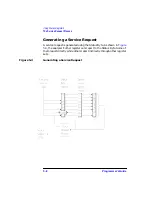
The analyzer's status system is based on the general status register
model shown in
. Most of the analyzer's register sets include
all of the registers shown in the model, although commands are not
always available for reading or writing a particular register. The
information flow within a register set starts at the condition register and
ends at the register summary bit (see
connections between the registers). This flow is controlled by setting bits
in the transition and enable registers.
Two register sets — the Status Byte and the Standard Event Status
Register — are 8-bits wide. All others are 16-bits wide, but the most
significant bit (bit 15) in the larger registers is always set to 0.
Figure 5-1
General Status Register Model
Summary of Contents for 8712ES
Page 11: ...1 1 1 Introduction to GPIB Programming ...
Page 27: ...2 1 2 Synchronizing the Analyzer and a Controller ...
Page 36: ...3 1 3 Passing Control ...
Page 39: ...4 1 4 Data Types and Encoding ...
Page 46: ...5 1 5 Using Status Registers ...
Page 71: ...6 1 6 Trace Data Transfers ...
Page 98: ...6 28 Programmer sGuide Trace Data Transfers Internal Measurement Arrays ...
Page 99: ...7 1 7 Using Graphics ...
Page 105: ...8 1 8 Front Panel Keycodes ...
Page 111: ...9 1 9 Introduction to SCPI ...
Page 129: ...10 1 10 Menu Map with SCPI Commands ...
Page 268: ...12 1 12 SCPI Conformance Information ...
Page 290: ...13 1 13 SCPI Error Messages ...

