5-6
Chapter 5
Data Processing Chain
Data Levels
Data Levels
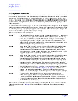
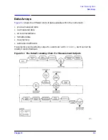
Different levels of data can be read out of the instrument. Refer to the data-processing
chain in
. The following sections describe the different types of data that are
available from the network analyzer.
Pre-Raw Data
This is the raw data without sampler correction or attenuator offsets applied. With raw
offsets turned off, the calibration coefficients generated can be transferred to an external
controller and used with the data gathered using the
OUTPPRE
commands. Refer to
“Example 2G: Take4 — Error Correction Processed on an External PC” on page 7-48
2-port measurement calibration is active, or Take4 mode is on, the four arrays refer to S
11
,
S
21
, S
12
, and S
22
respectively. This data is represented in real/imaginary pairs.
Raw Data
The basic measurement data, reflecting the stimulus parameters, IF averaging, and IF
bandwidth. If a full 2-port measurement calibration is activated, there are actually four
raw arrays kept: one for each raw S-parameter. The data can be output to a controller with
the
OUTPRAW
commands. Normally, only raw 1 is available, and it holds the current
parameter. If a 2-port measurement calibration is active, the four arrays refer to S
11
, S
21
,
S
12
, and S
22
respectively. This data is represented in real/imaginary pairs.
Error Coefficients
The results of a measurement calibration are arrays containing error coefficients. These
error coefficients are then used in the error-correction routines. Each array corresponds to
a specific error term in the error model. Your analyzer’s user’s guide details which error
coefficients are used for specific calibration types, as well as the arrays those coefficients
can be found in. Not all calibration types use all 12 arrays. The data is stored as
real/imaginary pairs.
Error-Corrected Data
This is the raw data with error-correction applied. The array represents the currently
measured parameter, and is stored in real/imaginary pairs. The error-corrected data can
be output to a controller with the
OUTPDATA;
command. The
OUTPMEMO;
command reads
the trace memory, if available. The trace memory also contains error-corrected data. Note
that neither raw nor error-corrected data reflect such post-processing functions as
electrical-delay offset, trace math, or time-domain gating.
Summary of Contents for 8719ES
Page 15: ...1 1 1 Alphabetical Command Reference ...
Page 293: ...2 1 2 Introduction to Instrument Control ...
Page 310: ...3 1 3 GPIB Programming ...
Page 334: ...4 1 4 Reading Analyzer Data ...
Page 343: ...5 1 5 Data Processing Chain ...
Page 350: ...6 1 6 Error Reporting ...
Page 364: ...7 1 7 Programming Examples ...
Page 502: ...A 1 A Preset Conditions ...
Page 517: ...B 1 B Command Listings ...

