7-70
Chapter 7
Programming Examples
Measurement Process Synchronization Examples
The status byte summarizes the error queue, as mentioned before. It also summarizes two
event-status registers that monitor specific conditions inside the instrument. The status
byte also has a bit (6) that is set when the instrument is issuing a service request over
GPIB, and a bit (0) that is set in the event-status register when the analyzer has data to
send out over GPIB. See
“Status Reporting” on page 6-3
for a discussion of the event-status
registers.
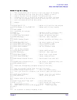
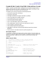
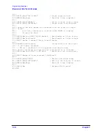
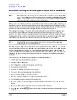
Example 4A: Using the Error Queue
The error queue holds up to 20 instrument errors and warnings in the order that they
occurred. Each time the analyzer detects an error condition, the analyzer displays a
message, and puts the error in the error queue. If there are any errors in the queue, bit 3 of
the status byte will be set. The errors can be read from the queue with the
OUTPERRO
command.
OUTPERRO
causes the analyzer to transmit the error number and message of the
oldest error in the queue.
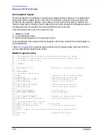
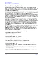
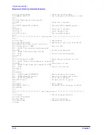
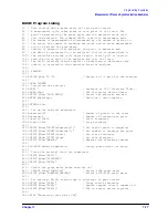
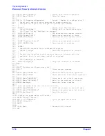
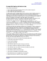
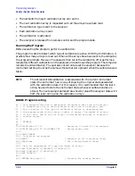
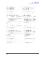
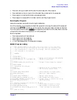
The following is an outline of the program's processing sequence:
• An I/O path is assigned for the analyzer.
• The system is initialized.
• The error-message string is allocated.
• The analyzer is released from remote control.
• The program begins an endless loop to read the error queue.
• The status byte is read with a serial poll.
• The program tests to see if an error is present in the queue.
• The error-queue bit is set.
• The program requests the content of the error queue.
• The error number and string are read.
• The error messages are printed until there are no more errors in the queue.
• The instrument is returned to local control.
• The controller emits a beep to attract the attention of the operator and resumes
searching for errors.
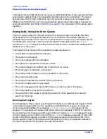
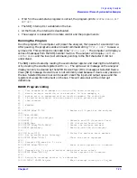
Running the Program
Run the program. The analyzer goes through the preset cycle. Nothing will happen at first.
The program is waiting for an error condition to activate the error queue. To cause an
error, press a blank softkey. The message
CAUTION: INVALID KEY
will appear on the
analyzer. The computer will beep and print out two error messages. The first line will be
the invalid key error message, and the second line will be the
NO ERRORS
message. To clear
the error queue, you can either loop until the
NO ERRORS
message is received, or wait until
the bit in the status register is cleared. In this case, we wait until the status bit in the
status register is clear. Note that while the program is running, the analyzer remains in
the local mode and the front-panel keys may be accessed.
Summary of Contents for 8719ES
Page 15: ...1 1 1 Alphabetical Command Reference ...
Page 293: ...2 1 2 Introduction to Instrument Control ...
Page 310: ...3 1 3 GPIB Programming ...
Page 334: ...4 1 4 Reading Analyzer Data ...
Page 343: ...5 1 5 Data Processing Chain ...
Page 350: ...6 1 6 Error Reporting ...
Page 364: ...7 1 7 Programming Examples ...
Page 502: ...A 1 A Preset Conditions ...
Page 517: ...B 1 B Command Listings ...

