7-104
Chapter 7
Programming Examples
Report Generation Examples
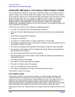
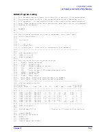
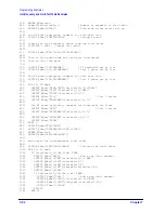
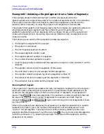
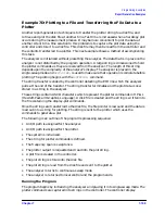
Example 7B: Controlling Peripherals Using Pass-Control Mode
NOTE
This example program will not work with HP BASIC for Windows.
If the analyzer is in pass-control mode and it receives a command telling it to plot, print,
control a power meter, or store/load to disk, it sets bit 1 in the event-status register to
indicate that it requires control of the bus. If the computer then uses the GPIB
pass-control command to pass control to the analyzer, the analyzer will take control of the
bus and access the peripheral. When the analyzer no longer requires control, it will pass
control back to the computer.
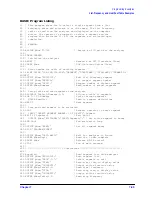
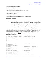
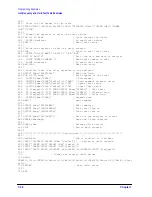
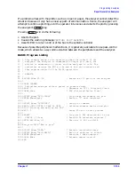
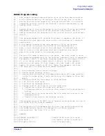
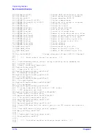
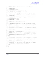
In this example, the pass-control mode is used to allow the network analyzer to dump a
screen display to a printer.
Pass-control mode allows the analyzer to control the printer while sending the screen
display to be printed. The analyzer requests control from the instrument controller and the
controller allows the analyzer to take control of the GPIB and dump the plot. The
instrument controller must not interact with the GPIB while this remote analyzer control
is taking place. Once the printer-dump operation is complete, the analyzer passes control
back to the controller and the controller continues programming the analyzer.
NOTE
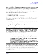
The analyzer assumes that the address of the computer is correctly stored in
its GPIB addresses menu under
. If this address is incorrect, control will not
return to the computer. Similarly, if control is passed to the analyzer while it
is in talker/listener mode, control will not return to the computer.
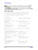
Control should not be passed to the analyzer before it has set event-status-register bit 1
making it Request Active Control. If the analyzer receives control before the bit is set,
control is passed immediately back to the controller.
When the analyzer becomes the active system controller, it is free to address devices to talk
and listen as required. The only functions denied the analyzer are the ability to assert the
interface clear line (IFC), and the remote line (REN). These are reserved for the master
system controller. As the active system controller, the analyzer can send and receive
messages from printers, plotters, and disk drives.
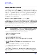
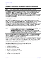
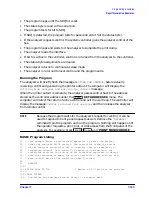
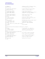
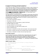
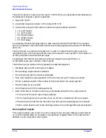
The following is an outline of the program's processing sequence:
• An I/O path is assigned for the analyzer.
• The system is initialized.
• The status registers are cleared.
• Bit 1 of ESR request control is set.
• The ESR interrupt for SRQ is enabled.
• The pass-control mode is enabled.
• The data is dumped to the printer.
Local
SET ADDRESSES
ADDRESS: CONTROLLER
Summary of Contents for 8719ES
Page 15: ...1 1 1 Alphabetical Command Reference ...
Page 293: ...2 1 2 Introduction to Instrument Control ...
Page 310: ...3 1 3 GPIB Programming ...
Page 334: ...4 1 4 Reading Analyzer Data ...
Page 343: ...5 1 5 Data Processing Chain ...
Page 350: ...6 1 6 Error Reporting ...
Page 364: ...7 1 7 Programming Examples ...
Page 502: ...A 1 A Preset Conditions ...
Page 517: ...B 1 B Command Listings ...

