T
able
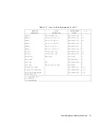
1-1.
Service
T
est
Equipment
Required
Equipment
Critical
Specications
Recommended
Model
Use
*
Spectrum
Analyzer
Freq.
A
ccuracy
67
Hz
HP
8563E
A,
T
Frequency
Counter
HP
5343A
P
Measuring
Receiver
HP
8902A
P
Oscilloscope
Bandwidth:
100
MHz
A
ccuracy:
10%
any
T
Digital
V
oltmeter
Resolution:
10
mV
any
T
T
ool
Kit
No
substitute
HP
part
number
08753-60023
T
P
ower
Meter
(HP-IB)
No
substitute
HP
436A
Opt.
022,
HP
437A
or
438A
A,
P
,
T
P
ower
Sensor
Frequency:
300
kHz-3
GHz,
50
HP
8482A
A,
P
,
T
P
ower
Sensor
(for
Option
006)
Frequency:
3
GHz-6
GHz
HP
8481A
Opt
006
A,
P
,
T
P
ower
Sensor
Frequency:
300
kHz-3
GHz,
75
HP
8483A
Opt.
H03
P
Photometer
T
ektronix
J16
A
Photometer
Probe
T
ektronix
J6503
A
Light
Occluder
T
ektronix
016-0305-00
A
CRT
Demagnetizer
or
Bulk
T
ape
Eraser
A
Printer
HP
ThinkJet,
DeskJet,
LaserJet
P
Disk
Drive
3.5-inch
HP
9122
Floppy
Disk
3.5-inch
HP
92192A
A
Calibration
Kit
Type-N,
50
No
substitute
HP
85032B
P
Calibration
Kit
Type-N,
75
No
substitute
HP
85036B
P
V
erication
Kit
7
mm
No
substitute
HP
85029B
P
Low
P
ass
Filter
>50
dB
@
2.96
Hz
and
passband
that
includes
800
MHz
HP
P/N
9135-0198
A
Step
Attenuator
110
dB
HP
8496A
P
Attenuators
(xed):
Return
loss:
32
dB
APC-7
20
dB
(2)
HP
8491A
Opt.
020
P
,
T
P
ower
Splitter
2-W
ay
,
50
HP
11667A
P
,
T
Minimum
Loss
P
ad
Type-N,
50
to
75
HP
11852B
P
,
T
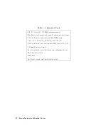
1-2
Service
Equipment
and
Analyzer
Options
Summary of Contents for 8752C
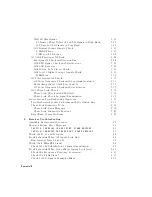
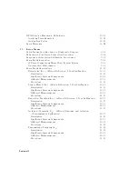
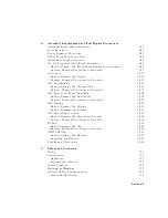
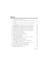
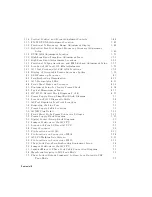
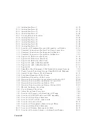
Page 22: ...Before Applying Power 15 6 Servicing 15 6 Index Contents 16 ...
Page 38: ......
Page 43: ...Figure 2 1 Measurement Uncertainty Window System Veri cation and Performance Tests 2 5 ...
Page 116: ......
Page 122: ...Figure 3 1 Location of Major Assemblies 3 6 Adjustments and Correction Constants ...
Page 176: ......
Page 192: ...4 16 Start Troubleshooting Here ...
Page 193: ......
Page 195: ...Figure 4 7 HP 8752C Overall Block Diagram 3 of 4 Option 006 4 20 Start Troubleshooting Here ...
Page 197: ......
Page 221: ...5 24 Power Supply Troubleshooting ...
Page 222: ......
Page 271: ...Figure 7 21 A14 Generated Digital Control Signals Source Troubleshooting 7 31 ...
Page 302: ......
Page 366: ......
Page 378: ...Figure 11 4 Typical ED Re ection Test Port 11 12 Error Terms ...
Page 380: ...Figure 11 5 Typical ES Re ection Test Port 11 14 Error Terms ...
Page 382: ...Figure 11 6 Typical ER Re ection Test Port 11 16 Error Terms ...
Page 386: ...Figure 11 9 Typical ET 11 20 Error Terms ...
Page 407: ...Figure 12 5 High Band Operation of the Source Theory of Operation 12 21 ...
Page 410: ...Figure 12 6 Receiver Functional Group standard and Option 003 12 24 Theory of Operation ...
Page 411: ...Figure 12 7 Receiver Functional Group Option 003 and 004 Theory of Operation 12 25 ...
Page 412: ...Figure 12 8 Receiver Functional Group Option 006 12 26 Theory of Operation ...
Page 413: ...Figure 12 9 Receiver Functional Group Option 004 and 006 Theory of Operation 12 27 ...
Page 416: ......
Page 419: ...Figure 13 1 Module Exchange Procedure Replaceable Parts 13 3 ...
Page 423: ...Major Assemblies Replaceable Parts 13 7 ...
Page 425: ...Front Panel Assemblies Replaceable Parts 13 9 ...
Page 427: ...Rear Panel Assemblies Replaceable Parts 13 11 ...
Page 429: ...Cables Top View Replaceable Parts 13 13 ...
Page 431: ...Front Panel Cables and Attaching Hardware Replaceable Parts 13 15 ...
Page 433: ...Rear Panel Cables and Attaching Hardware Replaceable Parts 13 17 ...
Page 435: ...Source and Sampler Parts Standard and Option 003 Replaceable Parts 13 19 ...
Page 437: ...Source and Sampler Parts Option 004 006 Replaceable Parts 13 21 ...
Page 439: ...Source and Sampler Parts Options 004 and 003 004 Replaceable Parts 13 23 ...
Page 441: ...Source and Sampler Parts Option 006 Replaceable Parts 13 25 ...
Page 443: ...Display Bezel Assembly Replaceable Parts 13 27 ...
Page 445: ...Chassis Parts Replaceable Parts 13 29 ...
Page 447: ...Top View of Attaching Hardware and Post Regulator Fuses Replaceable Parts 13 31 ...
Page 449: ...Bottom View of Attaching Hardware Replaceable Parts 13 33 ...
Page 488: ......

