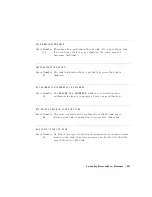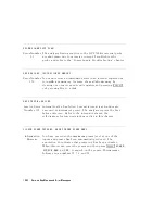
PROBE
POWER
SHUT
DOWN!
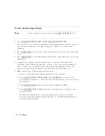
Error
Number
23
The
analyzer
biasing
supplies
to
the
HP
85024A
external
probe
are
shut
down
due
to
excessive
current.
Troubleshoot
the
probe
,
and
refer
to
the
\P
ower
Supply
Troubleshooting"
chapter
.
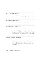
SAVE
FAILED.
INSUFFICIENT
MEMORY
Error
Number
151
Y
ou
cannot
store
an
instrument
state
in
an
internal
register
due
to
insucient
memory
.
Increase
the
available
memory
by
clearing
one
or
more
save/recall
registers
and
pressing
4
PRESET
5 ,
or
by
storing
les
to
a
disk.
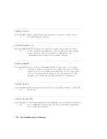
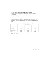
SELF
TEST
#n
FAILED
Service
Error
Number
112
Internal
test
#n
has
failed.
Several
internal
test
routines
are
executed
at
instrument
preset.
The
analyzer
reports
the
rst
failure
detected.
Refer
to
the
internal
tests
and
the
self-diagnose
feature
descriptions
earlier
in
this
chapter
.
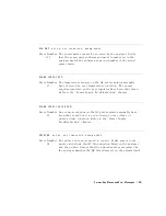
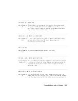
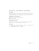
SOURCE
POWER
TRIPPED,
RESET
UNDER
POWER
MENU
Information
Message
Y
ou
have
exceeded
the
maximum
power
level
at
one
of
the
inputs
and
power
has
been
automatically
reduced.
The
annotation
P+
indicates
that
power
trip
has
been
activated.
When
this
occurs
,
reset
the
power
and
then
press
4
MENU
5
NNNNNNNNNNNNNNNNN
POWER
NNNNNNNNNNNNNNNNNNNNNNNNNNNNNNNNNNNNNNNNNNNNNNNNNNNNN
SOURCE
PWR
on
OFF
,
to
switch
on
the
power
.
This
message
follows
error
numbers
57,
58,
and
59.
10-62
Service
K
ey
Menus
and
Error
Messages
Summary of Contents for 8752C
Page 22: ...Before Applying Power 15 6 Servicing 15 6 Index Contents 16 ...
Page 38: ......
Page 43: ...Figure 2 1 Measurement Uncertainty Window System Veri cation and Performance Tests 2 5 ...
Page 116: ......
Page 122: ...Figure 3 1 Location of Major Assemblies 3 6 Adjustments and Correction Constants ...
Page 176: ......
Page 192: ...4 16 Start Troubleshooting Here ...
Page 193: ......
Page 195: ...Figure 4 7 HP 8752C Overall Block Diagram 3 of 4 Option 006 4 20 Start Troubleshooting Here ...
Page 197: ......
Page 221: ...5 24 Power Supply Troubleshooting ...
Page 222: ......
Page 271: ...Figure 7 21 A14 Generated Digital Control Signals Source Troubleshooting 7 31 ...
Page 302: ......
Page 366: ......
Page 378: ...Figure 11 4 Typical ED Re ection Test Port 11 12 Error Terms ...
Page 380: ...Figure 11 5 Typical ES Re ection Test Port 11 14 Error Terms ...
Page 382: ...Figure 11 6 Typical ER Re ection Test Port 11 16 Error Terms ...
Page 386: ...Figure 11 9 Typical ET 11 20 Error Terms ...
Page 407: ...Figure 12 5 High Band Operation of the Source Theory of Operation 12 21 ...
Page 410: ...Figure 12 6 Receiver Functional Group standard and Option 003 12 24 Theory of Operation ...
Page 411: ...Figure 12 7 Receiver Functional Group Option 003 and 004 Theory of Operation 12 25 ...
Page 412: ...Figure 12 8 Receiver Functional Group Option 006 12 26 Theory of Operation ...
Page 413: ...Figure 12 9 Receiver Functional Group Option 004 and 006 Theory of Operation 12 27 ...
Page 416: ......
Page 419: ...Figure 13 1 Module Exchange Procedure Replaceable Parts 13 3 ...
Page 423: ...Major Assemblies Replaceable Parts 13 7 ...
Page 425: ...Front Panel Assemblies Replaceable Parts 13 9 ...
Page 427: ...Rear Panel Assemblies Replaceable Parts 13 11 ...
Page 429: ...Cables Top View Replaceable Parts 13 13 ...
Page 431: ...Front Panel Cables and Attaching Hardware Replaceable Parts 13 15 ...
Page 433: ...Rear Panel Cables and Attaching Hardware Replaceable Parts 13 17 ...
Page 435: ...Source and Sampler Parts Standard and Option 003 Replaceable Parts 13 19 ...
Page 437: ...Source and Sampler Parts Option 004 006 Replaceable Parts 13 21 ...
Page 439: ...Source and Sampler Parts Options 004 and 003 004 Replaceable Parts 13 23 ...
Page 441: ...Source and Sampler Parts Option 006 Replaceable Parts 13 25 ...
Page 443: ...Display Bezel Assembly Replaceable Parts 13 27 ...
Page 445: ...Chassis Parts Replaceable Parts 13 29 ...
Page 447: ...Top View of Attaching Hardware and Post Regulator Fuses Replaceable Parts 13 31 ...
Page 449: ...Bottom View of Attaching Hardware Replaceable Parts 13 33 ...
Page 488: ......

