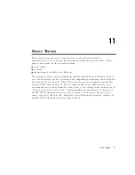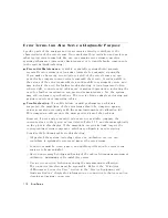
Error
T
erms
Can
Also
Serve
a
Diagnostic
Purpose
Specic
parts
of
the
analyzer
and
its
accessories
directly
contribute
to
the
characteristics
of
the
error
terms
.
Since
we
know
this
correlation
and
we
know
what
typical
error
terms
look
like
,
we
can
examine
error
terms
to
monitor
system
performance
(preventive
maintenance)
or
to
identify
faulty
components
in
the
system
(troubleshooting).
Preventive
Maintenance:
A
stable
,
repeatable
system
should
generate
repeatable
error
terms
over
long
time
intervals
,
for
example
,
six
months
.
If
you
make
a
hardcopy
record
or
plot)
of
the
error
terms
,
you
can
periodically
compare
current
error
terms
with
the
record.
A
sudden
shift
in
the
values
of
the
error
terms
reects
a
sudden
shift
in
systematic
errors
,
and
may
indicate
the
need
for
further
troubleshooting.
A
long-term
trend
often
reects
drift,
connector
and
cable
wear
,
or
gradual
degradation,
indicating
the
need
for
further
investigation
and
preventive
maintenance
.
Y
et,
the
system
may
still
conform
to
specications
.
The
cure
is
often
as
simple
as
cleaning
and
gaging
connectors
or
inspecting
cables
.
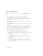
Troubleshooting:
If
a
subtle
failure
or
mild
performance
problem
is
suspected,
the
magnitude
of
the
error
terms
should
be
compared
against
values
generated
previously
with
the
same
instrument
and
calibration
kit.
This
comparison
will
produce
the
most
precise
view
of
the
problem.
However
,
if
previously
generated
values
are
not
available
,
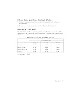
compare
the
current
values
to
the
typical
values
listed
in
T
able
11-2,
and
shown
graphically
on
the
plots
in
this
chapter
.
If
the
magnitude
exceeds
its
limit,
inspect
the
corresponding
system
component,
which
may
ultimately
need
replacing.
Consider
the
following
while
troubleshooting:
All
parts
of
the
system,
including
cables
and
calibration
devices
,
can
contribute
to
systematic
errors
and
impact
the
error
terms
.
Connectors
must
be
clean,
gaged,
and
within
specication
for
error
term
analysis
to
be
meaningful.
A
void
unnecessary
bending
and
exing
of
the
cables
following
measurement
calibration,
minimizing
cable
instability
errors
.
Use
good
connection
techniques
during
the
measurement
calibration.
The
connector
interface
must
be
repeatable
.
Refer
to
the
\Principles
of
Microwave
Connector
Care"
section
in
the
\Service
Equipment
and
Analyzer
Options"
chapter
for
information
on
connection
techniques
and
on
cleaning
and
gaging
connectors
.
11-2
Error
T
erms
Summary of Contents for 8752C
Page 22: ...Before Applying Power 15 6 Servicing 15 6 Index Contents 16 ...
Page 38: ......
Page 43: ...Figure 2 1 Measurement Uncertainty Window System Veri cation and Performance Tests 2 5 ...
Page 116: ......
Page 122: ...Figure 3 1 Location of Major Assemblies 3 6 Adjustments and Correction Constants ...
Page 176: ......
Page 192: ...4 16 Start Troubleshooting Here ...
Page 193: ......
Page 195: ...Figure 4 7 HP 8752C Overall Block Diagram 3 of 4 Option 006 4 20 Start Troubleshooting Here ...
Page 197: ......
Page 221: ...5 24 Power Supply Troubleshooting ...
Page 222: ......
Page 271: ...Figure 7 21 A14 Generated Digital Control Signals Source Troubleshooting 7 31 ...
Page 302: ......
Page 366: ......
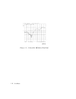
Page 378: ...Figure 11 4 Typical ED Re ection Test Port 11 12 Error Terms ...
Page 380: ...Figure 11 5 Typical ES Re ection Test Port 11 14 Error Terms ...
Page 382: ...Figure 11 6 Typical ER Re ection Test Port 11 16 Error Terms ...
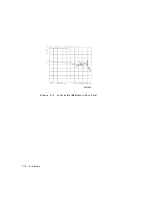
Page 386: ...Figure 11 9 Typical ET 11 20 Error Terms ...
Page 407: ...Figure 12 5 High Band Operation of the Source Theory of Operation 12 21 ...
Page 410: ...Figure 12 6 Receiver Functional Group standard and Option 003 12 24 Theory of Operation ...
Page 411: ...Figure 12 7 Receiver Functional Group Option 003 and 004 Theory of Operation 12 25 ...
Page 412: ...Figure 12 8 Receiver Functional Group Option 006 12 26 Theory of Operation ...
Page 413: ...Figure 12 9 Receiver Functional Group Option 004 and 006 Theory of Operation 12 27 ...
Page 416: ......
Page 419: ...Figure 13 1 Module Exchange Procedure Replaceable Parts 13 3 ...
Page 423: ...Major Assemblies Replaceable Parts 13 7 ...
Page 425: ...Front Panel Assemblies Replaceable Parts 13 9 ...
Page 427: ...Rear Panel Assemblies Replaceable Parts 13 11 ...
Page 429: ...Cables Top View Replaceable Parts 13 13 ...
Page 431: ...Front Panel Cables and Attaching Hardware Replaceable Parts 13 15 ...
Page 433: ...Rear Panel Cables and Attaching Hardware Replaceable Parts 13 17 ...
Page 435: ...Source and Sampler Parts Standard and Option 003 Replaceable Parts 13 19 ...
Page 437: ...Source and Sampler Parts Option 004 006 Replaceable Parts 13 21 ...
Page 439: ...Source and Sampler Parts Options 004 and 003 004 Replaceable Parts 13 23 ...
Page 441: ...Source and Sampler Parts Option 006 Replaceable Parts 13 25 ...
Page 443: ...Display Bezel Assembly Replaceable Parts 13 27 ...
Page 445: ...Chassis Parts Replaceable Parts 13 29 ...
Page 447: ...Top View of Attaching Hardware and Post Regulator Fuses Replaceable Parts 13 31 ...
Page 449: ...Bottom View of Attaching Hardware Replaceable Parts 13 33 ...
Page 488: ......

