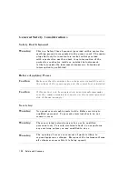
General
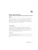
Safety
Considerations
Safety
Earth
Ground
W
arning
This
is
a
Safety
Class
I
product
(provided
with
a
protective
earthing
ground
incorporated
in
the
power
cord).
The
mains
plug
shall
only
be
inserted
in
a
socket
outlet
provided
with
a
protective
earth
contact.
Any
interruption
of
the
protective
conductor
,
inside
or
outside
the
instrument,
is
likely
to
make
the
instrument
dangerous
.
Intentional
interruption
is
prohibited.
Before
Applying
P
ower
Caution
Make
sure
that
the
analyzer
line
voltage
selector
switch
is
set
to
the
voltage
of
the
power
supply
and
the
correct
fuse
is
installed.
Caution
If
this
product
is
to
be
energized
via
an
autotransformer
make
sure
the
common
terminal
is
connected
to
the
neutral
(grounded
side
of
the
mains
supply).
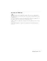
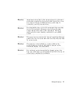
Servicing
W
arning
No
operator
serviceable
parts
inside
.
Refer
servicing
to
qualied
personnel.
T
o
prevent
electrical
shock,
do
not
remove
covers
.
W
arning
These
servicing
instructions
are
for
use
by
qualied
personnel
only
.
T
o
avoid
electrical
shock,
do
not
perform
any
servicing
unless
you
are
qualied
to
do
so
.
W
arning
The
opening
of
covers
or
removal
of
parts
is
likely
to
expose
dangerous
voltages
.
Disconnect
the
instrument
from
all
voltage
sources
while
it
is
being
opened.
15-6
Safety
and
Licensing
Summary of Contents for 8752C
Page 22: ...Before Applying Power 15 6 Servicing 15 6 Index Contents 16 ...
Page 38: ......
Page 43: ...Figure 2 1 Measurement Uncertainty Window System Veri cation and Performance Tests 2 5 ...
Page 116: ......
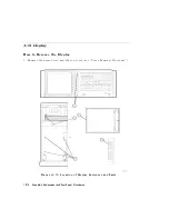
Page 122: ...Figure 3 1 Location of Major Assemblies 3 6 Adjustments and Correction Constants ...
Page 176: ......
Page 192: ...4 16 Start Troubleshooting Here ...
Page 193: ......
Page 195: ...Figure 4 7 HP 8752C Overall Block Diagram 3 of 4 Option 006 4 20 Start Troubleshooting Here ...
Page 197: ......
Page 221: ...5 24 Power Supply Troubleshooting ...
Page 222: ......
Page 271: ...Figure 7 21 A14 Generated Digital Control Signals Source Troubleshooting 7 31 ...
Page 302: ......
Page 366: ......
Page 378: ...Figure 11 4 Typical ED Re ection Test Port 11 12 Error Terms ...
Page 380: ...Figure 11 5 Typical ES Re ection Test Port 11 14 Error Terms ...
Page 382: ...Figure 11 6 Typical ER Re ection Test Port 11 16 Error Terms ...
Page 386: ...Figure 11 9 Typical ET 11 20 Error Terms ...
Page 407: ...Figure 12 5 High Band Operation of the Source Theory of Operation 12 21 ...
Page 410: ...Figure 12 6 Receiver Functional Group standard and Option 003 12 24 Theory of Operation ...
Page 411: ...Figure 12 7 Receiver Functional Group Option 003 and 004 Theory of Operation 12 25 ...
Page 412: ...Figure 12 8 Receiver Functional Group Option 006 12 26 Theory of Operation ...
Page 413: ...Figure 12 9 Receiver Functional Group Option 004 and 006 Theory of Operation 12 27 ...
Page 416: ......
Page 419: ...Figure 13 1 Module Exchange Procedure Replaceable Parts 13 3 ...
Page 423: ...Major Assemblies Replaceable Parts 13 7 ...
Page 425: ...Front Panel Assemblies Replaceable Parts 13 9 ...
Page 427: ...Rear Panel Assemblies Replaceable Parts 13 11 ...
Page 429: ...Cables Top View Replaceable Parts 13 13 ...
Page 431: ...Front Panel Cables and Attaching Hardware Replaceable Parts 13 15 ...
Page 433: ...Rear Panel Cables and Attaching Hardware Replaceable Parts 13 17 ...
Page 435: ...Source and Sampler Parts Standard and Option 003 Replaceable Parts 13 19 ...
Page 437: ...Source and Sampler Parts Option 004 006 Replaceable Parts 13 21 ...
Page 439: ...Source and Sampler Parts Options 004 and 003 004 Replaceable Parts 13 23 ...
Page 441: ...Source and Sampler Parts Option 006 Replaceable Parts 13 25 ...
Page 443: ...Display Bezel Assembly Replaceable Parts 13 27 ...
Page 445: ...Chassis Parts Replaceable Parts 13 29 ...
Page 447: ...Top View of Attaching Hardware and Post Regulator Fuses Replaceable Parts 13 31 ...
Page 449: ...Bottom View of Attaching Hardware Replaceable Parts 13 33 ...
Page 488: ......

