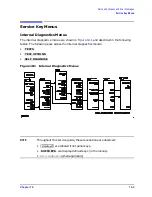
10-10
Chapter 10
Service Key Menus and Error Messages
Service Key Menus
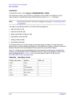
External Tests These tests require either external equipment and connections or
operator interaction of some kind to run. Tests 30 and 60 are comprehensive front panel
checks, more complete than test 12, that checks the front panel keys and knob entry.
19
ABUS Test
Tests analog bus accuracy, by measuring several analog bus reference voltages
(all nodes from the A10 digital IF). This runs only when selected.
20
FN Count
Uses the internal counter to count the A14 fractional-N VCO frequency (120 to
240 MHz) and the divided fractional-N frequency (100 kHz). It requires the
100 kHz signal from A12 and the counter gate signal from A10 to pass.
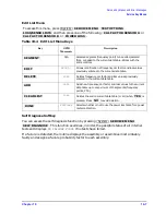
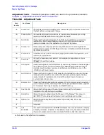
Table 10-6
External Tests
Test
Number
Test Name
Description
21
Port 1 Op Chk
“Step 2. Operator's Check” on page 4-6
. The procedure requires the
external connection of a short to PORT 1.
22
Port 2 Op Chk
Same as 21, but tests PORT 2 (for 8753ES). A through cable is required for the
8753ET.
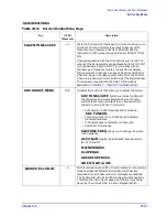
23
Fr Pan Seq
Tests the front panel knob entry and all A1 front panel keys, as well as the
front panel microprocessor on the A2 assembly. It prompts the user to rotate
the front panel knob, then press each key in an ordered sequence. It continues
to the next prompt only if the current prompt is correctly satisfied.
24
Fr Pan Diag
Similar to 23 above, but the user rotates the front panel knob or presses the
keys in any order. This test displays the command the instrument received.
25
ADC Hist
Factory use only.
26
Source Ex
Factory use only.
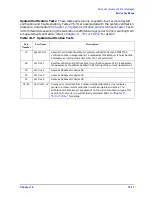
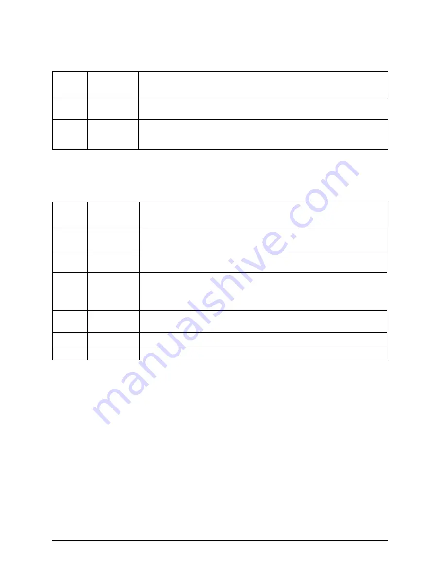
Table 10-5
Internal Tests
Test
Number
Test Name
Description
Summary of Contents for 8753ES
Page 14: ...Contents xiv Contents ...
Page 15: ...1 1 1 Service Equipment and Analyzer Options ...
Page 26: ...1 12 Chapter1 Service Equipment and Analyzer Options Service and Support Options ...
Page 27: ...2 1 2 System Verification and Performance Tests ...
Page 203: ...3 1 3 Adjustments and Correction Constants ...
Page 262: ...3 60 Chapter3 Adjustments and Correction Constants Sequences for Mechanical Adjustments ...
Page 263: ...4 1 4 Start Troubleshooting Here ...
Page 297: ...5 1 5 Power Supply Troubleshooting ...
Page 317: ......
Page 318: ...6 1 6 Digital Control Troubleshooting ...
Page 337: ...6 20 Chapter6 Digital Control Troubleshooting GPIB Failures ...
Page 338: ...7 1 7 Source Troubleshooting ...
Page 369: ...7 32 Chapter7 Source Troubleshooting Source Group Troubleshooting Appendix ...
Page 370: ...8 1 8 Receiver Troubleshooting ...
Page 381: ...8 12 Chapter8 Receiver Troubleshooting Troubleshooting When One or More Inputs Look Good ...
Page 382: ...9 1 9 Accessories Troubleshooting ...
Page 389: ...9 8 Chapter9 Accessories Troubleshooting Inspect the Error Terms ...
Page 390: ...10 1 10 Service Key Menus and Error Messages ...
Page 439: ...10 50 Chapter10 Service Key Menus and Error Messages Error Messages ...
Page 440: ...11 1 11 Error Terms ...
Page 451: ...11 12 Chapter11 Error Terms Error Correction ...
Page 452: ...12 1 12 Theory of Operation ...
Page 482: ...13 1 13 Replaceable Parts ...
Page 487: ...13 6 Chapter13 Replaceable Parts Ordering Information Figure 13 1 Module Exchange Procedure ...
Page 500: ...Chapter 13 13 19 Replaceable Parts Replaceable Part Listings Figure 13 7 8753ET Cables Top ...
Page 502: ...Chapter 13 13 21 Replaceable Parts Replaceable Part Listings Figure 13 8 8753ES Cables Top ...
Page 512: ...Chapter 13 13 31 Replaceable Parts Replaceable Part Listings Figure 13 13 8753ES Cables Front ...
Page 544: ...14 1 14 Assembly Replacement and Post Repair Procedures ...
Page 550: ...Chapter 14 14 7 Assembly Replacement and Post Repair Procedures Covers Figure 14 2 Covers ...
Page 597: ...14 54 Chapter14 Assembly Replacement and Post Repair Procedures Post Repair Procedures ...


