Chapter 10
10-13
Service Key Menus and Error Messages
Service Key Menus
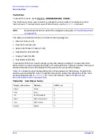
Display Tests These tests return a PASS/FAIL condition. All six amber front panel
LEDs will turn off if the test passes. Press
to exit the test. If any of the six LEDs
remain on, the test has failed.
Table 10-9
Display Tests
Test
Number
Test Name
Description
59
Disp/cpu com
Checks to confirm that the CPU can communicate with the A19 GSP board. The
CPU writes all zeros, all ones, and then a walking one pattern to the GSP and
reads them back. If the test fails, the CPU repeats the walking 1 pattern until
is pressed.
60
DRAM cell
Tests the DRAM on A19 by writing a test pattern to the DRAM and then
verifying that it can be read back.
61
Main VRAM
Tests the VRAM by writing all zeros to one location in each bank and then
writing all ones to one location in each bank. Finally a walking one pattern is
written to one location in each bank.
62
VRAM bank
Tests all the cells in each of the 4 VRAM banks.
63
VRAM/video
Verifies that the GSP is able to successfully perform both write and read shift
register transfers. It also checks the video signals LHSYNC, LVSYNC, and
LBLANK to verify that they are active and toggling.
64
RGB outputs
Confirms that the analog video signals are correct and it verifies their
functionality.
65
Inten DAC
Verifies that the intensity DAC can be set both low and high.
Preset
Preset
Summary of Contents for 8753ES
Page 14: ...Contents xiv Contents ...
Page 15: ...1 1 1 Service Equipment and Analyzer Options ...
Page 26: ...1 12 Chapter1 Service Equipment and Analyzer Options Service and Support Options ...
Page 27: ...2 1 2 System Verification and Performance Tests ...
Page 203: ...3 1 3 Adjustments and Correction Constants ...
Page 262: ...3 60 Chapter3 Adjustments and Correction Constants Sequences for Mechanical Adjustments ...
Page 263: ...4 1 4 Start Troubleshooting Here ...
Page 297: ...5 1 5 Power Supply Troubleshooting ...
Page 317: ......
Page 318: ...6 1 6 Digital Control Troubleshooting ...
Page 337: ...6 20 Chapter6 Digital Control Troubleshooting GPIB Failures ...
Page 338: ...7 1 7 Source Troubleshooting ...
Page 369: ...7 32 Chapter7 Source Troubleshooting Source Group Troubleshooting Appendix ...
Page 370: ...8 1 8 Receiver Troubleshooting ...
Page 381: ...8 12 Chapter8 Receiver Troubleshooting Troubleshooting When One or More Inputs Look Good ...
Page 382: ...9 1 9 Accessories Troubleshooting ...
Page 389: ...9 8 Chapter9 Accessories Troubleshooting Inspect the Error Terms ...
Page 390: ...10 1 10 Service Key Menus and Error Messages ...
Page 439: ...10 50 Chapter10 Service Key Menus and Error Messages Error Messages ...
Page 440: ...11 1 11 Error Terms ...
Page 451: ...11 12 Chapter11 Error Terms Error Correction ...
Page 452: ...12 1 12 Theory of Operation ...
Page 482: ...13 1 13 Replaceable Parts ...
Page 487: ...13 6 Chapter13 Replaceable Parts Ordering Information Figure 13 1 Module Exchange Procedure ...
Page 500: ...Chapter 13 13 19 Replaceable Parts Replaceable Part Listings Figure 13 7 8753ET Cables Top ...
Page 502: ...Chapter 13 13 21 Replaceable Parts Replaceable Part Listings Figure 13 8 8753ES Cables Top ...
Page 512: ...Chapter 13 13 31 Replaceable Parts Replaceable Part Listings Figure 13 13 8753ES Cables Front ...
Page 544: ...14 1 14 Assembly Replacement and Post Repair Procedures ...
Page 550: ...Chapter 14 14 7 Assembly Replacement and Post Repair Procedures Covers Figure 14 2 Covers ...
Page 597: ...14 54 Chapter14 Assembly Replacement and Post Repair Procedures Post Repair Procedures ...


