10-18
Chapter 10
Service Key Menus and Error Messages
Service Key Menus
SM4
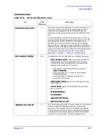
Automatically attempts to determine new pretune values
when the instrument encounters phase lock problems (for
example, “harmonic skip”). With
, the
frequencies and voltages do not change, like when they are
attempting to determine new pretune values, so
troubleshooting the phase-locked loop circuits is more
convenient. This function may also be turned off to avoid
pretune calibration errors in applications where there is a
limited frequency response in the R (reference) channel. For
example, in a high power test application, using band limited
filters for R channel phase locking.
N/A
Displays a phase lock sequence at the beginning of each band.
This sequence normally occurs very rapidly, making it
difficult to troubleshoot phase lock problems. Switching this
mode ON slows the process down, allowing you to inspect the
steps of the phase lock sequence (pretune, acquire, and track)
by pausing at each step. The steps are indicated on the
display, along with the channel (C1 or C2) and band number
(B1 through B13).
This mode can be used with PLL PAUSE to halt the process
at any step. It can also be used with the analog bus counter.
N/A
Used only with PLL DIAG mode.
indicates that it
will continuously cycle through all steps of the phase lock
sequence.
holds it at any step of interest. This
mode is useful for troubleshooting phase-locked loop
problems.
N/A
Provides access to the rest of the service modes keys.
SM5
Toggles the sampler correction routine ON, for normal
operation, or OFF, for diagnosis or adjustment purposes.
N/A
Normal operating condition and works in conjunction with IF
GAIN ON and OFF. The A10 assembly includes a switchable
attenuator section and an amplifier that amplifies low-level
4 kHz IF signals (for A and B inputs only). This mode allows
the A10 IF section to automatically determine if the
attenuator should be switched in or out. The switch occurs
when the A or B input signal is approximately
−
30 dBm.
N/A
Locks out the A10 IF attenuator sections for checking the
A10 IF gain amplifier circuits, regardless of the amplitude of
the A or B IF signal. Switches out both the A and B
attenuation circuits; they cannot be switched independently.
Be aware that input signal levels above
−
30 dBm at the
sampler input will saturate the ADC and cause measurement
errors.
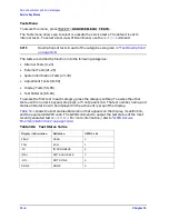
Table 10-11
Service Modes Menu Keys
Key
GPIB
Mnemonic
Description
PLL AUTO ON off
PLL AUTO OFF
PLL DIAG on OFF
PLL PAUSE
CONT
PAUSE
MORE
SAMPLER COR ON off
IF GAIN AUTO
IF GAIN ON
Summary of Contents for 8753ES
Page 14: ...Contents xiv Contents ...
Page 15: ...1 1 1 Service Equipment and Analyzer Options ...
Page 26: ...1 12 Chapter1 Service Equipment and Analyzer Options Service and Support Options ...
Page 27: ...2 1 2 System Verification and Performance Tests ...
Page 203: ...3 1 3 Adjustments and Correction Constants ...
Page 262: ...3 60 Chapter3 Adjustments and Correction Constants Sequences for Mechanical Adjustments ...
Page 263: ...4 1 4 Start Troubleshooting Here ...
Page 297: ...5 1 5 Power Supply Troubleshooting ...
Page 317: ......
Page 318: ...6 1 6 Digital Control Troubleshooting ...
Page 337: ...6 20 Chapter6 Digital Control Troubleshooting GPIB Failures ...
Page 338: ...7 1 7 Source Troubleshooting ...
Page 369: ...7 32 Chapter7 Source Troubleshooting Source Group Troubleshooting Appendix ...
Page 370: ...8 1 8 Receiver Troubleshooting ...
Page 381: ...8 12 Chapter8 Receiver Troubleshooting Troubleshooting When One or More Inputs Look Good ...
Page 382: ...9 1 9 Accessories Troubleshooting ...
Page 389: ...9 8 Chapter9 Accessories Troubleshooting Inspect the Error Terms ...
Page 390: ...10 1 10 Service Key Menus and Error Messages ...
Page 439: ...10 50 Chapter10 Service Key Menus and Error Messages Error Messages ...
Page 440: ...11 1 11 Error Terms ...
Page 451: ...11 12 Chapter11 Error Terms Error Correction ...
Page 452: ...12 1 12 Theory of Operation ...
Page 482: ...13 1 13 Replaceable Parts ...
Page 487: ...13 6 Chapter13 Replaceable Parts Ordering Information Figure 13 1 Module Exchange Procedure ...
Page 500: ...Chapter 13 13 19 Replaceable Parts Replaceable Part Listings Figure 13 7 8753ET Cables Top ...
Page 502: ...Chapter 13 13 21 Replaceable Parts Replaceable Part Listings Figure 13 8 8753ES Cables Top ...
Page 512: ...Chapter 13 13 31 Replaceable Parts Replaceable Part Listings Figure 13 13 8753ES Cables Front ...
Page 544: ...14 1 14 Assembly Replacement and Post Repair Procedures ...
Page 550: ...Chapter 14 14 7 Assembly Replacement and Post Repair Procedures Covers Figure 14 2 Covers ...
Page 597: ...14 54 Chapter14 Assembly Replacement and Post Repair Procedures Post Repair Procedures ...

