Chapter 10
10-49
Service Key Menus and Error Messages
Error Messages
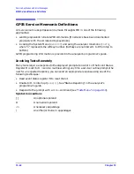
PWR MTR: NOT ON/CONNECTED OR WRONG ADDRS
Error Number 117
The power meter cannot be accessed by the analyzer. Verify that the power meter
address and model number set in the analyzer match the address and model number
of the actual power meter.
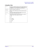
SAVE FAILED.INSUFFICIENT MEMORY
Error Number 151
You cannot store an instrument state in an internal register due to insufficient
memory. Increase the available memory by clearing one or more save/recall registers
and pressing
, or by storing files to a disk.
SELF TEST #n FAILED
Service Error
Number 112
Internal test #n has failed. Several internal test routines are executed at instrument
preset. The analyzer reports the first failure detected. Refer to the internal tests and
the self-diagnose feature descriptions earlier in this chapter.
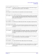
SOURCE POWER TURNED OFF, RESET UNDER POWER MENU
Information
Message
You have exceeded the maximum power level at one of the inputs and power has been
automatically reduced. The annotation P
⇓
indicates that power trip has been
activated. When this occurs, reset the power and then press
, to switch on the power. This message follows error
numbers 57, 58, and 59.
SWEEP MODE CHANGED TO CW TIME SWEEP
Error Number 187
If you select external source auto or manual instrument mode and you do not also
select CW mode, the analyzer is automatically switched to CW.
TEST ABORTED
Error Number 113
You have prematurely stopped a service test.
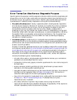
TROUBLE!CHECK SETUP AND START OVER
Service Error
Number 115
Your equipment setup for the adjustment procedure in progress is not correct. Check
the setup diagram and instructions in
“Source Pretune Correction Constants
. Start the procedure again.
WRONG DISK FORMAT, INITIALIZE DISK
Error Number 77
You have attempted to store, load, or read file titles, but your disk format does not
conform to the Logical Interchange Format (LIF). You must initialize the disk before
reading or writing to it.
Preset
Power
SOURCE PWR on OFF
Summary of Contents for 8753ES
Page 14: ...Contents xiv Contents ...
Page 15: ...1 1 1 Service Equipment and Analyzer Options ...
Page 26: ...1 12 Chapter1 Service Equipment and Analyzer Options Service and Support Options ...
Page 27: ...2 1 2 System Verification and Performance Tests ...
Page 203: ...3 1 3 Adjustments and Correction Constants ...
Page 262: ...3 60 Chapter3 Adjustments and Correction Constants Sequences for Mechanical Adjustments ...
Page 263: ...4 1 4 Start Troubleshooting Here ...
Page 297: ...5 1 5 Power Supply Troubleshooting ...
Page 317: ......
Page 318: ...6 1 6 Digital Control Troubleshooting ...
Page 337: ...6 20 Chapter6 Digital Control Troubleshooting GPIB Failures ...
Page 338: ...7 1 7 Source Troubleshooting ...
Page 369: ...7 32 Chapter7 Source Troubleshooting Source Group Troubleshooting Appendix ...
Page 370: ...8 1 8 Receiver Troubleshooting ...
Page 381: ...8 12 Chapter8 Receiver Troubleshooting Troubleshooting When One or More Inputs Look Good ...
Page 382: ...9 1 9 Accessories Troubleshooting ...
Page 389: ...9 8 Chapter9 Accessories Troubleshooting Inspect the Error Terms ...
Page 390: ...10 1 10 Service Key Menus and Error Messages ...
Page 439: ...10 50 Chapter10 Service Key Menus and Error Messages Error Messages ...
Page 440: ...11 1 11 Error Terms ...
Page 451: ...11 12 Chapter11 Error Terms Error Correction ...
Page 452: ...12 1 12 Theory of Operation ...
Page 482: ...13 1 13 Replaceable Parts ...
Page 487: ...13 6 Chapter13 Replaceable Parts Ordering Information Figure 13 1 Module Exchange Procedure ...
Page 500: ...Chapter 13 13 19 Replaceable Parts Replaceable Part Listings Figure 13 7 8753ET Cables Top ...
Page 502: ...Chapter 13 13 21 Replaceable Parts Replaceable Part Listings Figure 13 8 8753ES Cables Top ...
Page 512: ...Chapter 13 13 31 Replaceable Parts Replaceable Part Listings Figure 13 13 8753ES Cables Front ...
Page 544: ...14 1 14 Assembly Replacement and Post Repair Procedures ...
Page 550: ...Chapter 14 14 7 Assembly Replacement and Post Repair Procedures Covers Figure 14 2 Covers ...
Page 597: ...14 54 Chapter14 Assembly Replacement and Post Repair Procedures Post Repair Procedures ...

