3-56
Chapter 3
Adjustments and Correction Constants
Sequences for Mechanical Adjustments
How to Set Up the High/Low Band Transition Adjustments
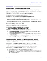
1. Press
(where X is the sequence number).
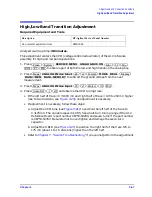
2. Observe the VCO tuning trace:
• If the left half of trace = 0
±
1000 mV and right half of trace = 100 to 200 mV higher
(one to two divisions): no adjustment is necessary.
• If the adjustment is necessary, follow these steps:
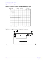
a. Remove the upper-rear bumpers and top cover, using a TORX screwdriver.
b. Adjust the VCO tune (A12 C85) to position the left half of the trace to 0
±
125 mV.
This is a very sensitive adjustment where the trace could easily go off of the
screen.
c. Adjust the HBLB (A12 R68) to position the right half of the trace 125 to 175 mV
(about 1 to 1.5 divisions) higher than the left half.
• Refer to
Chapter 7 , “Source Troubleshooting,”
if you cannot perform the adjustment.
How to Set Up the Fractional-N Spur Avoidance and FM Sideband
Adjustment
1. Press
(where X is the sequence number).
2. Remove the upper-rear corner bumpers and the top cover, using a TORX screwdriver.
3. Follow the directions on the analyzer display and make all of the API adjustments.
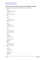
Sequence Contents
Sequence for the High/Low Band Transition Adjustment
— Sequence HBLBADJ sets the hi-band to low-band switch point. —
PRESET
SYSTEM
SERVICE MENU
ANALOG BUS ON
START 11 M/u
STOP 21 M/u
MEAS
ANALOG IN 22 x1 (A12 GND)
DISPLAY
DATA > MEM
DATA
−
MEM
MEAS
ANALOG IN 23 x1 (VCO TUNE)
MKR 11 M/u
SCALE/REF .1 x1
Preset
SEQ X HBLBADJ
Preset
SEQUENCE X APIADJ
Summary of Contents for 8753ES
Page 14: ...Contents xiv Contents ...
Page 15: ...1 1 1 Service Equipment and Analyzer Options ...
Page 26: ...1 12 Chapter1 Service Equipment and Analyzer Options Service and Support Options ...
Page 27: ...2 1 2 System Verification and Performance Tests ...
Page 203: ...3 1 3 Adjustments and Correction Constants ...
Page 262: ...3 60 Chapter3 Adjustments and Correction Constants Sequences for Mechanical Adjustments ...
Page 263: ...4 1 4 Start Troubleshooting Here ...
Page 297: ...5 1 5 Power Supply Troubleshooting ...
Page 317: ......
Page 318: ...6 1 6 Digital Control Troubleshooting ...
Page 337: ...6 20 Chapter6 Digital Control Troubleshooting GPIB Failures ...
Page 338: ...7 1 7 Source Troubleshooting ...
Page 369: ...7 32 Chapter7 Source Troubleshooting Source Group Troubleshooting Appendix ...
Page 370: ...8 1 8 Receiver Troubleshooting ...
Page 381: ...8 12 Chapter8 Receiver Troubleshooting Troubleshooting When One or More Inputs Look Good ...
Page 382: ...9 1 9 Accessories Troubleshooting ...
Page 389: ...9 8 Chapter9 Accessories Troubleshooting Inspect the Error Terms ...
Page 390: ...10 1 10 Service Key Menus and Error Messages ...
Page 439: ...10 50 Chapter10 Service Key Menus and Error Messages Error Messages ...
Page 440: ...11 1 11 Error Terms ...
Page 451: ...11 12 Chapter11 Error Terms Error Correction ...
Page 452: ...12 1 12 Theory of Operation ...
Page 482: ...13 1 13 Replaceable Parts ...
Page 487: ...13 6 Chapter13 Replaceable Parts Ordering Information Figure 13 1 Module Exchange Procedure ...
Page 500: ...Chapter 13 13 19 Replaceable Parts Replaceable Part Listings Figure 13 7 8753ET Cables Top ...
Page 502: ...Chapter 13 13 21 Replaceable Parts Replaceable Part Listings Figure 13 8 8753ES Cables Top ...
Page 512: ...Chapter 13 13 31 Replaceable Parts Replaceable Part Listings Figure 13 13 8753ES Cables Front ...
Page 544: ...14 1 14 Assembly Replacement and Post Repair Procedures ...
Page 550: ...Chapter 14 14 7 Assembly Replacement and Post Repair Procedures Covers Figure 14 2 Covers ...
Page 597: ...14 54 Chapter14 Assembly Replacement and Post Repair Procedures Post Repair Procedures ...


