Chapter 4
4-7
Start Troubleshooting Here
Step 2. Operator’s Check
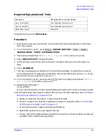
Required Equipment and Tools
Analyzer warm-up time: 30 minutes.
Procedure
1. Disconnect all devices, peripherals, and accessories (including adapters and limiters)
from the analyzer.
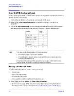
2. To run the test for port 1, press
.
3. The display should show “
TEST 21 Port 1 Op Chk”
in the active entry area.
4. Press
to begin the test.
5. At the prompt, connect the short to the port indicated. Make sure the connection is
tight.
6. Press .
7. The test is a sequence of subtests. At the end of the subtests, the test title and result
will be displayed. If all tests pass successfully, the overall test status will be
PASS
. If any
test fails, the overall test status will be
FAIL
.
8. To run the test for port 2, press the step
key. The display should show “
TEST 22
Port 2 Op Chk
” in the active entry area.
9. Repeat steps 4 through 7.
For an 8753ET:
You will be prompted to connect a cable between the Reflection and Transmission ports.
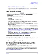
10.If both tests pass, the analyzer is about 80% verified. If either test fails, refer to
Faulty Group Isolation” on page 4-10
, or:
a. Make sure that the connection is tight. Repeat the test.
b. Visually inspect the connector interfaces and clean if necessary (refer to
of Microwave Connector Care” on page 1-7
c. Verify that the short meets published specifications.
d. Substitute another short, and repeat the test.
e. Finally, refer to the detailed tests located in this section, or fault-isolation procedures
located in the troubleshooting sections.
Description
HP/Agilent Part or Model Number
Short (for 8753ES)
Part of 85031B Calibration Kit
Short (for 8753ET)
Part of 85032B Calibration Kit
Cable: 50
Ω
, Type-N
8120-4781
Preset
PRESET: FACTORY
Preset
System
SERVICE MENU TESTS EXTERNAL TESTS
EXECUTE TEST
CONTINUE
Summary of Contents for 8753ES
Page 14: ...Contents xiv Contents ...
Page 15: ...1 1 1 Service Equipment and Analyzer Options ...
Page 26: ...1 12 Chapter1 Service Equipment and Analyzer Options Service and Support Options ...
Page 27: ...2 1 2 System Verification and Performance Tests ...
Page 203: ...3 1 3 Adjustments and Correction Constants ...
Page 262: ...3 60 Chapter3 Adjustments and Correction Constants Sequences for Mechanical Adjustments ...
Page 263: ...4 1 4 Start Troubleshooting Here ...
Page 297: ...5 1 5 Power Supply Troubleshooting ...
Page 317: ......
Page 318: ...6 1 6 Digital Control Troubleshooting ...
Page 337: ...6 20 Chapter6 Digital Control Troubleshooting GPIB Failures ...
Page 338: ...7 1 7 Source Troubleshooting ...
Page 369: ...7 32 Chapter7 Source Troubleshooting Source Group Troubleshooting Appendix ...
Page 370: ...8 1 8 Receiver Troubleshooting ...
Page 381: ...8 12 Chapter8 Receiver Troubleshooting Troubleshooting When One or More Inputs Look Good ...
Page 382: ...9 1 9 Accessories Troubleshooting ...
Page 389: ...9 8 Chapter9 Accessories Troubleshooting Inspect the Error Terms ...
Page 390: ...10 1 10 Service Key Menus and Error Messages ...
Page 439: ...10 50 Chapter10 Service Key Menus and Error Messages Error Messages ...
Page 440: ...11 1 11 Error Terms ...
Page 451: ...11 12 Chapter11 Error Terms Error Correction ...
Page 452: ...12 1 12 Theory of Operation ...
Page 482: ...13 1 13 Replaceable Parts ...
Page 487: ...13 6 Chapter13 Replaceable Parts Ordering Information Figure 13 1 Module Exchange Procedure ...
Page 500: ...Chapter 13 13 19 Replaceable Parts Replaceable Part Listings Figure 13 7 8753ET Cables Top ...
Page 502: ...Chapter 13 13 21 Replaceable Parts Replaceable Part Listings Figure 13 8 8753ES Cables Top ...
Page 512: ...Chapter 13 13 31 Replaceable Parts Replaceable Part Listings Figure 13 13 8753ES Cables Front ...
Page 544: ...14 1 14 Assembly Replacement and Post Repair Procedures ...
Page 550: ...Chapter 14 14 7 Assembly Replacement and Post Repair Procedures Covers Figure 14 2 Covers ...
Page 597: ...14 54 Chapter14 Assembly Replacement and Post Repair Procedures Post Repair Procedures ...


