Chapter 7
7-27
Source Troubleshooting
Phase Lock Error
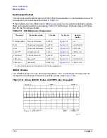
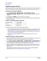
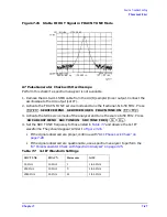
Figure 7-25
Stable HI OUT Signal in FRACN TUNE Mode
A7 Pulse Generator Check with Oscilloscope
Perform this check if a spectrum analyzer is not available.
1. Remove the A4-to-A11 SMB cable from the A4 (R) sampler/mixer output. Connect the
oscilloscope to the A4 output (1st IF).
2. Activate the FRACN TUNE service mode and tune the fractional-N to 50 MHz. Press
.
3. Activate the SRC service mode of the analyzer and tune the source to 50 MHz. Press
.
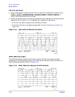
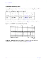
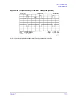
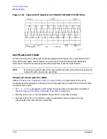
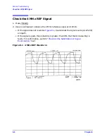
4. Set the SRC TUNE frequency to those listed in
and observe the 1st IF
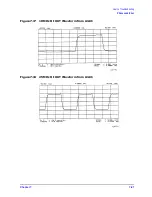
waveforms. They should appear similar to
• If the signals observed are proper, continue with
• If the signals observed are questionable, use a spectrum analyzer to perform the
“A7 Pulse Generator Check with Spectrum Analyzer” on page 7-25
Table 7-7
1st IF Waveform Settings
SRC
TUNE FRACN Harmonic 1st
IF
50 MHz
50 MHz
1
1 to 6 MHz
250 MHz
50 MHz
5
1 to 6 MHz
2550 MHz
50 MHz
51
1 to 6 MHz
System
SERVICE MENU SERVICE MODES FRACN TUNE ON
50
M/
µ
SRC ADJUST MENU SRC TUNE ON SRC TUNE FREQ
50
M/
µ
Summary of Contents for 8753ES
Page 14: ...Contents xiv Contents ...
Page 15: ...1 1 1 Service Equipment and Analyzer Options ...
Page 26: ...1 12 Chapter1 Service Equipment and Analyzer Options Service and Support Options ...
Page 27: ...2 1 2 System Verification and Performance Tests ...
Page 203: ...3 1 3 Adjustments and Correction Constants ...
Page 262: ...3 60 Chapter3 Adjustments and Correction Constants Sequences for Mechanical Adjustments ...
Page 263: ...4 1 4 Start Troubleshooting Here ...
Page 297: ...5 1 5 Power Supply Troubleshooting ...
Page 317: ......
Page 318: ...6 1 6 Digital Control Troubleshooting ...
Page 337: ...6 20 Chapter6 Digital Control Troubleshooting GPIB Failures ...
Page 338: ...7 1 7 Source Troubleshooting ...
Page 369: ...7 32 Chapter7 Source Troubleshooting Source Group Troubleshooting Appendix ...
Page 370: ...8 1 8 Receiver Troubleshooting ...
Page 381: ...8 12 Chapter8 Receiver Troubleshooting Troubleshooting When One or More Inputs Look Good ...
Page 382: ...9 1 9 Accessories Troubleshooting ...
Page 389: ...9 8 Chapter9 Accessories Troubleshooting Inspect the Error Terms ...
Page 390: ...10 1 10 Service Key Menus and Error Messages ...
Page 439: ...10 50 Chapter10 Service Key Menus and Error Messages Error Messages ...
Page 440: ...11 1 11 Error Terms ...
Page 451: ...11 12 Chapter11 Error Terms Error Correction ...
Page 452: ...12 1 12 Theory of Operation ...
Page 482: ...13 1 13 Replaceable Parts ...
Page 487: ...13 6 Chapter13 Replaceable Parts Ordering Information Figure 13 1 Module Exchange Procedure ...
Page 500: ...Chapter 13 13 19 Replaceable Parts Replaceable Part Listings Figure 13 7 8753ET Cables Top ...
Page 502: ...Chapter 13 13 21 Replaceable Parts Replaceable Part Listings Figure 13 8 8753ES Cables Top ...
Page 512: ...Chapter 13 13 31 Replaceable Parts Replaceable Part Listings Figure 13 13 8753ES Cables Front ...
Page 544: ...14 1 14 Assembly Replacement and Post Repair Procedures ...
Page 550: ...Chapter 14 14 7 Assembly Replacement and Post Repair Procedures Covers Figure 14 2 Covers ...
Page 597: ...14 54 Chapter14 Assembly Replacement and Post Repair Procedures Post Repair Procedures ...


