10-6
Chapter 10
Service Key Menus and Error Messages
Service Key Menus
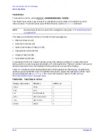
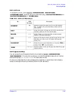
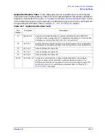
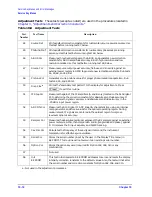
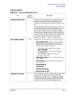
Test Options Menu
To access this menu, press
.
Table 10-3
Test Options Menu Keys
Key
GPIB
Mnemonic
Description
N/A
Accesses softkeys that affect the way tests (routines) run, or
supply necessary additional data.
TESR1
Resumes the test from where it was stopped.
TO2
Toggles the repeat function on and off. When the function is
ON, the selected test will run 10,000 times unless you press
any key to stop it. The analyzer shows the current number of
passes and fails.
TO1
Toggles the record function on and off. When the function is
on, certain test results are sent to a printer via GPIB. This is
especially useful for correction constants. The instrument
must be in system controller mode or pass control mode to
print (refer to your analyzer’s user’s guide for more
information on printing).
N/A
Selects either NORMal or SPeCiaL (tighter) limits for the
operator's check. The SPCL limits are useful for a guard
band.
PWRLOSS
Selects whether or not to use the power loss table for a power
meter calibration.
N/A
Accesses the power loss/sensor lists menu that contains the
following softkeys:
(
USESENS<A|B>
) selects the A or
B power sensor calibration factor list for use in power
meter calibration measurements.
(
CALFSENA
) accesses the
Edit List menu to allow modification of the calibration
data table for power sensor A.
(
CALFSENB
) accesses the
Edit List menu to allow modification of the calibration
data table for power sensor B.
(
POWLLIST
) accesses the Edit List
menu to allow modification of the external power loss
data table that corrects coupled-arm power loss when a
directional coupler samples the RF output.
N/A
Generates printed graphs of verification results when
activated during a system verification.
System
SERVICE MENU TEST OPTIONS
TEST OPTIONS
CONTINUE TEST
REPEAT on OFF
RECORD on OFF
LIMITS [NORM/SPCL]
PWR LOSS on OFF
LOSS/SENSR LISTS
USE SENSOR A/B
CAL FACTOR SENSOR A
CAL FACTOR SENSOR B
POWER LOSS
DUMP GRAPH
Summary of Contents for 8753ES
Page 14: ...Contents xiv Contents ...
Page 15: ...1 1 1 Service Equipment and Analyzer Options ...
Page 26: ...1 12 Chapter1 Service Equipment and Analyzer Options Service and Support Options ...
Page 27: ...2 1 2 System Verification and Performance Tests ...
Page 203: ...3 1 3 Adjustments and Correction Constants ...
Page 262: ...3 60 Chapter3 Adjustments and Correction Constants Sequences for Mechanical Adjustments ...
Page 263: ...4 1 4 Start Troubleshooting Here ...
Page 297: ...5 1 5 Power Supply Troubleshooting ...
Page 317: ......
Page 318: ...6 1 6 Digital Control Troubleshooting ...
Page 337: ...6 20 Chapter6 Digital Control Troubleshooting GPIB Failures ...
Page 338: ...7 1 7 Source Troubleshooting ...
Page 369: ...7 32 Chapter7 Source Troubleshooting Source Group Troubleshooting Appendix ...
Page 370: ...8 1 8 Receiver Troubleshooting ...
Page 381: ...8 12 Chapter8 Receiver Troubleshooting Troubleshooting When One or More Inputs Look Good ...
Page 382: ...9 1 9 Accessories Troubleshooting ...
Page 389: ...9 8 Chapter9 Accessories Troubleshooting Inspect the Error Terms ...
Page 390: ...10 1 10 Service Key Menus and Error Messages ...
Page 439: ...10 50 Chapter10 Service Key Menus and Error Messages Error Messages ...
Page 440: ...11 1 11 Error Terms ...
Page 451: ...11 12 Chapter11 Error Terms Error Correction ...
Page 452: ...12 1 12 Theory of Operation ...
Page 482: ...13 1 13 Replaceable Parts ...
Page 487: ...13 6 Chapter13 Replaceable Parts Ordering Information Figure 13 1 Module Exchange Procedure ...
Page 500: ...Chapter 13 13 19 Replaceable Parts Replaceable Part Listings Figure 13 7 8753ET Cables Top ...
Page 502: ...Chapter 13 13 21 Replaceable Parts Replaceable Part Listings Figure 13 8 8753ES Cables Top ...
Page 512: ...Chapter 13 13 31 Replaceable Parts Replaceable Part Listings Figure 13 13 8753ES Cables Front ...
Page 544: ...14 1 14 Assembly Replacement and Post Repair Procedures ...
Page 550: ...Chapter 14 14 7 Assembly Replacement and Post Repair Procedures Covers Figure 14 2 Covers ...
Page 597: ...14 54 Chapter14 Assembly Replacement and Post Repair Procedures Post Repair Procedures ...

