14-4
Chapter 14
Assembly Replacement and Post-Repair Procedures
Replacing an Assembly
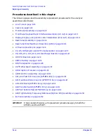
Procedures described in this chapter
The following pages describe assembly replacement procedures for the analyzer
assemblies listed below:
•
•
•
Front Panel Assembly on page 14-8
•
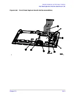
Front Panel Keyboard and Interface Assemblies (A1, A2) on page 14-10
•
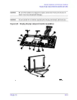
Display, Display Lamp and Inverter Assemblies (A18, A27) on page 14-12
•
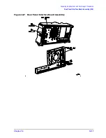
Rear Panel Assembly on page 14-14
•
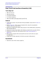
Rear Panel Interface Board Assembly (A16) on page 14-16
•
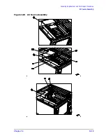
A3 Source Assembly on page 14-18
•
A4, A5, A6 Samplers and A7 Pulse Generator on page 14-20
•
A8, A10, A11, A12, A13, A14 Card Cage Boards on page 14-22
•
•
•
A15 Preregulator on page 14-28
•
A17 Motherboard Assembly on page 14-30
•
A19 Graphics Processor on page 14-34
•
A20 Disk Drive Assembly on page 14-36
•
A21, A22 Test Port Couplers (8753ES Only) on page 14-40
•
A21 Dual Directional Coupler (8753ET Only) on page 14-42
•
A23 LED Board (8753ES Only) on page 14-44
•
A24 Transfer Switch (8753ES Only) on page 14-46
•
A25 Test Set Interface (8753ES Only) on page 14-48
•
A26 High Stability Frequency Reference (Option 1D5) Assembly on page 14-50
•
IMPORTANT
Unless noted otherwise, all replacement procedures apply to both the
8753ES and the 8753ET.
Summary of Contents for 8753ES
Page 14: ...Contents xiv Contents ...
Page 15: ...1 1 1 Service Equipment and Analyzer Options ...
Page 26: ...1 12 Chapter1 Service Equipment and Analyzer Options Service and Support Options ...
Page 27: ...2 1 2 System Verification and Performance Tests ...
Page 203: ...3 1 3 Adjustments and Correction Constants ...
Page 262: ...3 60 Chapter3 Adjustments and Correction Constants Sequences for Mechanical Adjustments ...
Page 263: ...4 1 4 Start Troubleshooting Here ...
Page 297: ...5 1 5 Power Supply Troubleshooting ...
Page 317: ......
Page 318: ...6 1 6 Digital Control Troubleshooting ...
Page 337: ...6 20 Chapter6 Digital Control Troubleshooting GPIB Failures ...
Page 338: ...7 1 7 Source Troubleshooting ...
Page 369: ...7 32 Chapter7 Source Troubleshooting Source Group Troubleshooting Appendix ...
Page 370: ...8 1 8 Receiver Troubleshooting ...
Page 381: ...8 12 Chapter8 Receiver Troubleshooting Troubleshooting When One or More Inputs Look Good ...
Page 382: ...9 1 9 Accessories Troubleshooting ...
Page 389: ...9 8 Chapter9 Accessories Troubleshooting Inspect the Error Terms ...
Page 390: ...10 1 10 Service Key Menus and Error Messages ...
Page 439: ...10 50 Chapter10 Service Key Menus and Error Messages Error Messages ...
Page 440: ...11 1 11 Error Terms ...
Page 451: ...11 12 Chapter11 Error Terms Error Correction ...
Page 452: ...12 1 12 Theory of Operation ...
Page 482: ...13 1 13 Replaceable Parts ...
Page 487: ...13 6 Chapter13 Replaceable Parts Ordering Information Figure 13 1 Module Exchange Procedure ...
Page 500: ...Chapter 13 13 19 Replaceable Parts Replaceable Part Listings Figure 13 7 8753ET Cables Top ...
Page 502: ...Chapter 13 13 21 Replaceable Parts Replaceable Part Listings Figure 13 8 8753ES Cables Top ...
Page 512: ...Chapter 13 13 31 Replaceable Parts Replaceable Part Listings Figure 13 13 8753ES Cables Front ...
Page 544: ...14 1 14 Assembly Replacement and Post Repair Procedures ...
Page 550: ...Chapter 14 14 7 Assembly Replacement and Post Repair Procedures Covers Figure 14 2 Covers ...
Page 597: ...14 54 Chapter14 Assembly Replacement and Post Repair Procedures Post Repair Procedures ...


