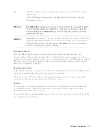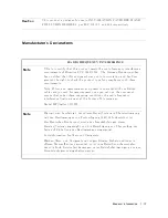
The
A
C
sym
b ol
is
used
to
indicate
the
required
nature
of
the
line
mo
dule
input
p o
w
er.
The
C-Tick
mark
is
a
registered
trademark
of
the
Australian
Sp ectrum
Management
Agency
.
W
arning
The
W
ARNING
sign
denotes
a
hazard.
It
calls
attention
to
a
procedure,
which,
if
not
correctly
performedor
adhered
to,
couldresult
in
personal
injury
.
Do
not
proceed
bey
ond
a
W
ARNING
sign
until
the
indicated
conditions
are
fully
understood
and
met.
Caution
A
Caution
note
denotes
a
hazard.
It
calls
attention
to
a
pro cedure,
that,
if
not
correctly
p erformed
or
adhered
to,
could
result
in
damage
to
or
destruction
of
the
pro duct.
Do
not
pro ceed
b ey
ond
a
Caution
note
un
til
the
indicated
conditions
are
fully
understo o d
and
met.
Safety
Earth
Ground
This
is
a
Safet
y
Class
I
pro duct
(provided
with
a
protective
earthing
terminal).
An
unin
terruptible
safety
earth
ground
m
ust
b e
pro
vided
from
the
main
p o
w
er
source
to
the
pro duct
input
wiring
terminals,
p o
w
er,
cord,
or
supplied
p o
w
er
cord
set.
Whenev
er
it
is
likely
that
the
protection
has
b een
impaired,
the
pro duct
m
ust
b e
made
inop erative
and
secured
against
an
y
unin
tended
op eration.
Before
Applying
P
o
w
er
V
erify
that
the
pro duct
is
congured
to
match
the
a
v
ailable
main
p o
w
er
source.
Refer
to
the
input
p o
w
er
conguration
instructions
pro
vided
in
this
man
ual.
If
this
pro duct
is
to
b e
used
with
an
autotransformer
make
sure
the
common
terminal
is
connected
to
the
neutral
(grounded)
side
of
the
main
supply
.
Servicing
An
y
servicing,
adjustmen
t,
maintenance,
or
repair
of
this
pro duct
m
ust
b e
p erformed
only
b
y
qualied
p ersonnel.
Capacitors
inside
this
pro duct
may
still
b e
c
harged
ev
en
when
disconnected
from
their
p o
w
er
source.
T
o
a
v
oid
a
re
hazard,
replacemen
t
fuses
m
ust
ha
v
e
the
required
curren
t
rating
and
b e
of
the
t
yp e
sp ecied
in
this
man
ual.
General
Information
1-3
Summary of Contents for 8757D
Page 8: ......
Page 13: ...Figure 1 2 HP 8757D Scalar Network Analyzer and Accessories Supplied General Information 1 5 ...
Page 27: ...General Information 1 19 ...
Page 39: ...Figure 2 4 Rack Mounting the Analyzer Installation 2 9 ...
Page 41: ...Figure 2 5 Analyzer to HP Agilent 8350 Sweep Oscillator Interconnections Installation 2 11 ...
Page 43: ...Figure 2 7 Analyzer to HP Agilent 8360 Series Synthesizer Interconnections Installation 2 13 ...
Page 44: ...Figure 2 8 Analyzer to HP Agilent 83750 Series Synthesizer Interconnections 2 14 Installation ...
Page 45: ...Figure 2 9 Rear Panel Display Connectors Installation 2 15 ...
Page 49: ...Figure 2 11 HP IB Connectors Signals and Pin Configuration Installation 2 19 ...
Page 52: ......
Page 55: ......
Page 56: ......
Page 57: ......
Page 58: ......
Page 59: ......
Page 60: ......
Page 61: ......
Page 62: ......
Page 63: ......
Page 64: ......
Page 65: ......
Page 66: ......
Page 67: ......
Page 68: ......
Page 69: ......
Page 70: ......
Page 71: ......
Page 72: ......
Page 73: ......
Page 74: ......
Page 75: ......
Page 76: ......
Page 77: ......
Page 78: ......

