background image

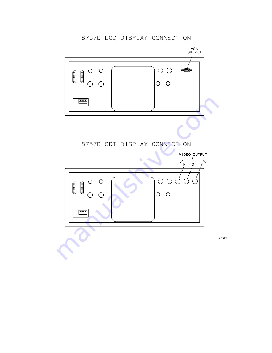
Figure

2-9.

Rear

P

anel

Display

Connectors

Installation

2-15

Summary of Contents for 8757D

Page 1: ...Network Analyzer Manufacturing Part Number 08757 90109 Printed in USA Print Date March 2005 Supersedes November 2000 Agilent Technologies Inc 1993 2000 2005 Silicon Investigations Repair Information Contact Us 920 955 3693 www siliconinvestigations com ...

Page 2: ...OR FOR INCIDENTAL OR CONSEQUENTIAL DAMAGES IN CONNECTION WITH THE FURNISHING USE OR PERFORMANCE OF THIS DOCUMENT OR ANY INFORMATION CONTAINED HEREIN SHOULD AGILENT AND THE USER HAVE A SEPARATE WRITTEN AGREEMENT WITH WARRANTY TERMS COVERING THE MATERIAL IN THIS DOCUMENT THAT CONFLICT WITH THESE TERMS THE WAR RANTY TERMS IN THE SEPARATE AGREEMENT WILL CONTROL DFARS Restricted Rights Notice If softwa...

Page 3: ...tation from the Web download the PDF file from the Agilent web site Go to http www agilent com Enter the document s part number located on the title page in the Quick Search box Click GO Click on the hyperlink for the document Click the printer icon located in the tool bar ...

Page 4: ...87 44 22 Belgium tel 32 0 2 404 9340 alt 32 0 2 404 9000 fax 32 0 2 404 9395 Denmark tel 45 7013 1515 alt 45 7013 7313 fax 45 7013 1555 Finland tel 358 10 855 2100 fax 358 0 10 855 2923 France tel 0825 010 700 alt 33 0 1 6453 5623 fax 0825 010 701 Germany tel 01805 24 6333 alt 01805 24 6330 fax 01805 24 6336 Ireland tel 353 0 1 890 924 204 alt 353 0 1 890 924 206 fax 353 0 1 890 924 024 Israel tel...

Page 5: ...uction 2 1 Initial Inspection 2 2 Operating Environment 2 3 Electrostatic Discharge 2 4 Power Requirements 2 5 Checking the Line Voltage and Fuse 2 5 Checking the Power Cable 2 6 Equipment Required But Not Supplied 2 7 AC Detection 2 7 Firmware Compatibility 2 7 Rack Mounting 2 8 Connecting the Analyzer to a Source 2 10 External Modulation 2 10 Other Con gurations 2 10 Connecting the Analyzer to a...

Page 6: ... B Softkey Menu Structure Maps B 1 C Performing an External Calibration C 1 D Measurement Applications D 1 Remote Operation HP IB Programming Notes 1 HP 8757D Quick Reference Guide 1 HP 8757D with HP 90000 Series 200 300 BASIC 1 HP 8757D with HP Vectra QuickBasic 4 5 1 HP 8757D with HP Vectra QuickC 2 5 1 In Case of Di culty Contents 1 Manual Operation 2 Line Power 2 Error Codes 2 System Operation...

Page 7: ...rement Memory Memory 9 Cursor Search 9 On Site Service 9 Main Error Codes 10 Power Calibration Error Messages 13 Detector Error Messages HP 85037A B only 14 On Site Service Calibration 14 Connector Care Principles of Microwave Connector Care Quick Reference Card Glossary Contents 3 ...

Page 8: ......

Page 9: ...erations serial numbers analyzer description power calibrator option available options speci cations operating characteristics manufacturer s radio interference declaration manufacturer s sound emission declaration manufacturer s ISO declaration ordering accessories and supplies General Information 1 1 ...

Page 10: ...may cause product damage Safety Symbols General This product was designed and manufactured in accordance with international safety standards Before you operate this analyzer review the product and related documentation Become familiar with safety markings and instructions L Instruction manual symbol the product will be marked with this symbol when it is necessary for the user to refer to the instr...

Page 11: ...erminal An uninterruptible safety earth ground must be provided from the main power source to the product input wiring terminals power cord or supplied power cord set Whenever it is likely that the protection has been impaired the product must be made inoperative and secured against any unintended operation Before Applying Power Verify that the product is con gured to match the available main powe...

Page 12: ...e the serial number plate Figure 1 1 attached to the analyzer back panel The rst four digits followed by a letter are the serial number pre x The last ve digits are the sequential su x which are unique to each instrument Figure 1 1 Typical Serial Number Label 1 4 General Information ...

Page 13: ...Figure 1 2 HP 8757D Scalar Network Analyzer and Accessories Supplied General Information 1 5 ...

Page 14: ...er can simultaneously drive both the internal display and one external monitor color or monochrome if compatible with the analyzer s scan rate and video levels Peripherals You can use the analyzer to control external printers plotters and sources through the system interface A printer and plotter bu er speeds measurements by returning control to the analyzer while data prints Calibration Data and ...

Page 15: ...ts A B and R and adds an internal power calibrator The power can be precisely controlled in 1 dB increments from 20 to 050 dBm Option 908 Rack Mount Without Handles This option supplies a rack mount kit containing a pair of anges and the necessary hardware to mount the analyzer with handles detached in an equipment rack that has 482 6 mm 19 in horizontal spacing See chapter 2 for installation inst...

Page 16: ...he serial number tag provides a three year return to HP calibration service You can order this option only at time of purchase Option 1BN MIL STD 45662A Calibration This option provides an instrument calibration and a certi cate of calibration in full compliance with MIL STD 45662A Option 1BP MIL STD 45662A Calibration with Data This option provides an instrument calibration a certi cate of calibr...

Page 17: ...hour of continuous operation Unless otherwise noted corrected limits are given when speci cations are subject to optimization with error correction routines General Requirements General requirements listed in Table 1 2 de ne speci cations required of the source for proper analyzer operation Operating Characteristics Operating characteristics listed in Table 1 3 are non warranted parameters They ar...

Page 18: ...drive signal turns the HP 11665B fully on for minimum insertion loss The 8360 and 8370 synthesized sweepers have the capability of modulating signals so an external modulator such as the 11665B is not necessary when using the 8360 8370 series Marker Accuracy The marker frequency accuracy is 0 1 PPM of the marker frequency plus the source marker frequency accuracy Frequency 27 778 kHz 612 Hz Symmet...

Page 19: ...037 Series precision detectors Frequency 50 MHz 60 1 MHz Output Power DC mode Range 20 to 050 dBm Accuracy at 0 dBm 60 05 dB SWR 1 05 typical Modes of Operation DC Mode unmodulated AC Mode Modulation Frequency 27 778 60 012 kHz On O Ratio 40 dB typical Symmetry 50 6 1 typical Connector Type N f Accessories Included Adapter Type N m to 3 5 mm f 1All speci cation apply at 25 65 C unless otherwise no...

Page 20: ...wave amplitude modulation Frequency 27 778 kHz 620 Hz 30 dB on o ratio 45 to 55 symmetry Sweep Voltage Sweep In Horizontal sweep voltage 0 to 10 V or a pulse signal 0 to 10 V from an HP 83750 Series source provided to the analyzer s SWEEP IN 0 10V rear panel input You can use other sweep voltages by using the analyzer s non standard sweep mode Marker and Marker Blanking Poz Z Blank Blanking and ma...

Page 21: ...r is 60 mV Display Mode Scale Resolution Display Range Vertical Resolution dBm 0 1 to 20 dB div 080 to 0130 dBm2 0 003 dB3 dB ratio 0 1 to 20 dB div 0150 to 150 dBm4 0 006 dB3 Normalized Ratio 0 1 to 20 dB div 0180 to 180 dB 0 01 dB SWR 0 02 to 10 units div 1 0 to 37 0 0 01 at 1 0 1 at 10 0 27 at 30 AUX 0 025 to 5V div 010 to 10V 0 001 V Color Settings Up to 8 operator selected colors for CRT LCD ...

Page 22: ...width Normalization Traces are stored and normalized with the highest resolution independent of display scale division or o set Calibration data is interpolated when you decrease the frequency span with adaptive normalization engaged Limit Lines Any limit combination of at or sloped lines or single points up to 12 segments can be displayed on channels 1 and 2 You can store limit lines in save reca...

Page 23: ...Used with HP 8350 sweep oscillators and HP 8340 8341 or 8360 synthesized sweepers when controlled by the HP 8757 system interface to stop the sweep at band crossings and at the end of sweep Sweep In Accepts the horizontal sweep voltage usually provided by the source CRT Video Output Three BNC connectors used to drive external monitors with the following characteristics 75 input impedance R G B wit...

Page 24: ...ramming codes Interrupts The following conditions generate HP IB service interrupts SRQs Front panel key pressed Illegal command Instrument self test error Limit test fails Operation sweep or plot completes System Interface The 8757 system interface is a dedicated HP IB port used exclusively by the analyzer to control and extract information from a swept source digital plotter printer or other dev...

Page 25: ...n open set ups the user must ensure that under these operating conditions the radio frequency interference limits are met at the border of his premises Model HP Agilent 8757D Note Hiermit wird bescheinigt dass dieses Gerat System in Ubereinstimmung mit den Bestimmungen von Postverfugung 1046 84 funkentstort ist Der Deutschen Bundespost wurde das Inverkehrbringen dieses Gerates Systems angezeight u...

Page 26: ...position 70 dB Sound Pressure Lp 70 dB A At Operator Position Normal Operation According to ISO 7779 Type Test Model HP Agilent 8757D Note Herstellerbescheinigung Diese Information steht im Zusammenhang mit den Anforderungen der Maschinenlarminformationsverordnung vom 18 Januar 1991 Schalldruckpegel Lp 70 dB A Am Arbeitsplatz Normaler Betrieb Nach DIN 45635 T 19 Typprufung 1 18 General Information...

Page 27: ...General Information 1 19 ...

Page 28: ...afe Workstation and Table 1 4 for a list available parts To order a listed item provide the part number and the quantity required send the order to the nearest Agilent Technologies sales and service o ce listed at the back of this chapter 1 20 General Information ...

Page 29: ...010 1140 Adapter1 type N male to 3 5 mm female 08485 60005 HP IB Cable 10833A Fuses 2 5 A 250 V NTD FE UL 2110 0083 1 5 A 250 V NTD FE UL 2110 0043 Rack Mount Handles Front Handles standard 5062 3990 Rack Mounting without Handles Option 908 5062 3978 Rack Mounting with Handles Option 913 5062 4072 ESD Supplies Conductive Table Mat with 15 ft Ground Wire 9300 0797 Wrist Strap to Table Mat Grounding...

Page 30: ...22 INTERCON FIELD OPERATIONS Headquarters Australia Canada Agilent Technologies Company Agilent Technologies Australia Ltd Agilent Technologies Canada Ltd 3495 Deer Creek Road 31 41 Joseph Street 17500 South Service Road Palo Alto California USA Blackburn Victoria 3130 Trans Canada Highway 94304 1316 61 3 895 2895 Kirkland Quebec H9J 2X8 415 857 5027 Canada 514 697 4232 China Japan Singapore China...

Page 31: ...rge hazards and precautions line voltage selector switch fuse inspection power cable inspection Introduction This section provides installation instructions for your HP Agilent 8757D scalar network analyzer This section also includes information about initial inspection damage claims preparation for using the analyzer packaging storage and shipment Installation 2 1 ...

Page 32: ...ipping the instrument are located at the end of this chapter Shipment Contents A complete shipment consists of one box see chapter 1 for part numbers The box will contain one each of the following HP Agilent 8757D scalar network analyzer HP IB cable power cable type N to 3 5 mm adapter Option 002 only front handles operating manual service manual Serial Numbers Agilent Technologies makes frequent ...

Page 33: ...ed To meet the speci cations listed in chapter 1 you must operate this instrument within the following limits Temperature 0 to 55 C 32 to 131 F Altitude 4572 metres 15 000 feet Humidity 5 to 95 at 25 to 40 C 77 to 104 F Protect the analyzer from temperature extremes which can cause internal condensation Cooling Leave 10 cm 4 in of room at the rear of the cabinet and 7 6 cm 3 in at the sides of the...

Page 34: ...ive table mat and wrist strap combination 2 A conductive oor mat and heel strap combination Figure 2 2 Example of a Static Safe Work Station Reducing Damage Caused by ESD The following can help reduce ESD damage that occurs during testing and servicing operations Before you connect a coaxial cable to an analyzer connector for the rst time each day momentarily ground the cable center and outer cond...

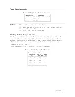
Page 35: ...election card and the fuse are located in the AC power module on the rear panel of the analyzer see Figure 2 3 For continued protection against re hazard replace line fuse only with the same type and ratings The use of other fuses or materials is prohibited To select the line voltage and fuse see chapter 1 for fuse part numbers 1 Measure the AC line voltage 2 Using the values in Table 2 2 follow t...

Page 36: ...provided with a protective earth contact Any interruption of the protective conductor inside or outside of the product is likely to make the product dangerous Intentional interruption is prohibited IEC 348 clauses 17 3 3 c 17 3 4 Install the instrument so that the ON OFF switch is readily identi able and is easily reached by the operator The ON OFF switch or the detachable power cord is the instru...

Page 37: ...square wave modulation capability at 27 778 kHz Firmware Compatibility Table 2 3 lists the sweeper rmware revisions required for complete compatibility with the HP Agilent 8757D Table 2 3 Firmware Revisions HP Agilent Sweeper Firmware Revision 8350B 6 83522A 3 83525A B 3 83540A B 3 83545A 3 83550A 6 83570A 3 83572A B 6 83590A 6 83592A B C 6 83594A 6 83595A 6 83595C All 83596A All 83596B All 83597A...

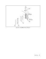
Page 38: ...k mount ange 2 with four panhead screws 4 per side 5 Remove the feet and tilt stands 5 6 Save the at head screws and front handle assemblies for reuse Rack Mounting with Front Handles Option 913 Option 913 instruments are shipped with a rack mount kit The kit supplies the hardware and installation instructions to prepare a standard instrument with handles to mount on an equipment rack with 482 6 m...

Page 39: ...Figure 2 4 Rack Mounting the Analyzer Installation 2 9 ...

Page 40: ...n W O System Interface Connected Connection Function With System Interface Connected 8340A 2302A Pulse Input Pulse Input Pulse 2320A AM Input Shift Pulse AM Input1 8341A all AM Input Shift Pulse AM Input1 8340B all Pulse Input Pulse Input Pulse1 8341B all Pulse Input Pulse Pulse Input Pulse1 1 The correct function is programmed automatically Other Configurations If you operate the analyzer without...

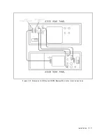
Page 41: ...Figure 2 5 Analyzer to HP Agilent 8350 Sweep Oscillator Interconnections Installation 2 11 ...

Page 42: ...Figure 2 6 Analyzer to HP Agilent 8340 and 8341 Series Synthesizer Interconnections 2 12 Installation ...

Page 43: ...Figure 2 7 Analyzer to HP Agilent 8360 Series Synthesizer Interconnections Installation 2 13 ...

Page 44: ...Figure 2 8 Analyzer to HP Agilent 83750 Series Synthesizer Interconnections 2 14 Installation ...

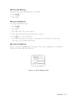
Page 45: ...Figure 2 9 Rear Panel Display Connectors Installation 2 15 ...

Page 46: ...te 16 716 mS vertical time 31 41 kHz horizontal refresh rate 31 840 S horizontal time 75 ohm video input impedance video analog amplitude 0 7 Vp p negagive true TTL logic for vertical and horizontal synchronization Setting the HP IB Address In remote mode a controller communicates through the HP IB identifying each instrument on the bus by its HP IB address Because of this each instrument on an HP...

Page 47: ...ys the current address 3 Using the front panel keypad enter the new address 4 Press 4ENT5 to terminate the entry The CRT displays the new address Turning the line switch o or presetting the instrument does not a ect this address Recording the Address Figure 2 10 shows an HP IB label see chapter 1 for ordering information available for recording instrument HP IB addresses Figure 2 10 HP IB Address ...

Page 48: ...h or without additional instruments You can then remotely operate the analyzer with the same control except for power line switch and internal tests as with local operation The controller maintains remote control by sending commands to and receiving data from the analyzer over the HP IB Cables Connect instruments on the HP IB or on the system interface using HP IB cables The cables are available i...

Page 49: ...Figure 2 11 HP IB Connectors Signals and Pin Configuration Installation 2 19 ...

Page 50: ...ls follow these instructions 1 Wrap the instrument in heavy paper 2 Use a strong shipping container A double wall carton made of 350 pound test material is adequate 3 Use enough shock absorbing material 3 to 4 inch layer around all sides of the instrument to provide a rm cushion and prevent movement inside the container Protect the control panel with cardboard Seal the shipping container securely ...

Page 51: ...When making inquiries either by correspondence or by telephone please refer to the instrument by model number and full serial number Installation 2 21 ...

Page 52: ......

Page 53: ...ls with an LCD base display must use rmware revision 7 0 or greater they are not interchangeable Check the rear panel of the instrument to determine the type of display Instruments with the LCD based display are equipped with a VGA connector on the rear panel so that an external monitor may be connected CRT based instruments are equipped with three BNC connectors RGB for this purpose See Figure 2 ...

Page 54: ...uick reference guide introductory programming guides with example programs and programming codes In Case of Difficulty see white tab This section contains information on what to do if you encounter a problem with the analyzer It provides suggestions for minor problems that do not involve defects in the internal circuitry The service manual chapter 8 provides in depth troubleshooting information 3 ...

Page 55: ......

Page 56: ......

Page 57: ......

Page 58: ......

Page 59: ......

Page 60: ......

Page 61: ......

Page 62: ......

Page 63: ......

Page 64: ......

Page 65: ......

Page 66: ......

Page 67: ......

Page 68: ......

Page 69: ......

Page 70: ......

Page 71: ......

Page 72: ......

Page 73: ......

Page 74: ......

Page 75: ......

Page 76: ......

Page 77: ......

Page 78: ......

Reviews: