HP-IB
Connectors
and
Cables
A
tutorial
description
of
HP-IB
is
a
v
ailable
from
Agilent
T
ec
hnologies
(see
c
hapter
1
for
ordering
information).
See
also
\Remote
Op eration,"
whic
h
describ es
the
analyzer's
HP-IB
capabilities.
Figure
2-11
illustrates
an
HP-IB
connector
pin
conguration
and
signals.
Connectors
The
analyzer
has
t
w
o
rear
panel
HP-IB
connectors:
1.
The
8757
System
In
terface
(J1).
This
remote
programming
in
terface
lets
y
ou
connect
the
analyzer
to
the
HP-IB
connector
of
compatible
instrumen
ts
and
use
the
analyzer
(in
either
lo
cal
or
remote
op eration)
to
con
trol
a
plotter,
prin
ter,
or
source.
This
dedicated
HP-IB
p ort
is
used
exclusiv
ely
b
y
the
analyzer;
do
not
connect
a
con
troller
to
this
connector.
2.
The
HP
In
terface
Bus
(J2).
This
remote
programming
in
terface
lets
y
ou
connect
the
analyzer
to
a
con
troller
via
HP-IB
with
or
without
additional
instrumen
ts.
Y
ou
can
then
remotely
op erate
the
analyzer
with
the
same
con
trol
(except
for
p o
w
er,
line
switch,
and
in
ternal
tests)
as
with
lo
cal
op eration.
The
con
troller
maintains
remote
con
trol
b
y
sending
commands
to
and
receiving
data
from
the
analyzer
o
v
er
the
HP-IB.
Cables
Connect
instrumen
ts
on
the
HP-IB
or
on
the
system
in
terface
using
HP-IB
cables.
The
cables
are
a
v
ailable
in
lengths
from
0.5m
(1.6
ft)
to
4m
(13.2
ft).
See
c
hapter
1
\General
Information"
for
ordering
information.
Y
ou
may
connect
up
to
fteen
instrumen
ts
in
parallel
on
the
HP-IB
or
the
system
in
terface,
but
if
the
system
cable
is
to
o
long
or
if
the
accum
ulated
cable
length
b et
w
een
instrumen
ts
is
to
o
long,
the
system
cannot
maintain
the
prop er
data
and
con
trol
lines
v
oltage
lev
els
and
timing
relationships
(see
T
able
2-5 ).
T
able
2-5.
HP-IB
Cabling
Restrictions
Numb er
of
Instrumen
ts
in
the
System
1
Maximum
Cable
Length
(m/ft)
2
4/12
>
2
2/6
2
na
20/65
3
1
Including
the
analyzer.
2
T
o
each
instrument.
3
Betw
een
all
units.
2-18
Installation
Summary of Contents for 8757D
Page 8: ......
Page 13: ...Figure 1 2 HP 8757D Scalar Network Analyzer and Accessories Supplied General Information 1 5 ...
Page 27: ...General Information 1 19 ...
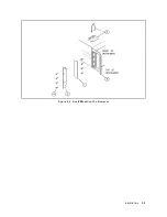
Page 39: ...Figure 2 4 Rack Mounting the Analyzer Installation 2 9 ...
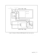
Page 41: ...Figure 2 5 Analyzer to HP Agilent 8350 Sweep Oscillator Interconnections Installation 2 11 ...
Page 43: ...Figure 2 7 Analyzer to HP Agilent 8360 Series Synthesizer Interconnections Installation 2 13 ...
Page 44: ...Figure 2 8 Analyzer to HP Agilent 83750 Series Synthesizer Interconnections 2 14 Installation ...
Page 45: ...Figure 2 9 Rear Panel Display Connectors Installation 2 15 ...
Page 49: ...Figure 2 11 HP IB Connectors Signals and Pin Configuration Installation 2 19 ...
Page 52: ......
Page 55: ......
Page 56: ......
Page 57: ......
Page 58: ......
Page 59: ......
Page 60: ......
Page 61: ......
Page 62: ......
Page 63: ......
Page 64: ......
Page 65: ......
Page 66: ......
Page 67: ......
Page 68: ......
Page 69: ......
Page 70: ......
Page 71: ......
Page 72: ......
Page 73: ......
Page 74: ......
Page 75: ......
Page 76: ......
Page 77: ......
Page 78: ......


