Chapter 6
109
Configuring IO Interfaces
Configuring the USB Interface
Configuring the USB Interface
This procedure is used to configure the USB interface except as directed for the
following measurement hardware:
•
Agilent 82357 USB/GPIB Interface
: If you are using a Agilent 82357
"Configuring the USB/GPIB Interface" (page 105)
.
The instructions in this chapter assume that the USB interface is installed in
your PC and is working.
NOTE
The purpose of this chapter is to guide you through the specific setup required to
get your computer and instrument configured properly. For more detailed
information on GPIB IO configuration, refer to the documentation for the IO
Libraries Suite (click the
IO Control
icon, then select
Documentation >
Connectivity
).
To configure the USB interface:
Connect your USB instruments to the USB interface in the computer. Power on the
PC and the instruments.
On the
Series 6000A/7000A
Oscilloscopes, verify the I/O Controller is set to USB.
If it is not set to USB, press Utility > I/O > Controller XX (where XX is either
GPIB, LAN or USB), use the Entry knob labelled with a circular arrow to point the
screen arrow to USB and press the Controller button. For the
Series 6000L
Oscilloscopes, see scope documentation.
Run Connection Expert
1. Run Connection Expert.
Click the
IO Control
icon in the task bar, then click
Agilent Connection
Expert
, or click
Start > (All) Programs > Agilent IO Libraries Suite >
Agilent Connection Expert.
Connection Expert will automatically detect and configure the interface and
instruments and will assign names and other default configuration settings
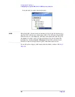
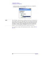
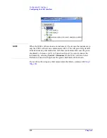
2. To verify that the computer recognized the instrument, expand
USB0
in the
Instrument I/O on this PC
section. Connection Expert will list all instruments
and their addresses. A green checkmark will be shown to verify that the
instrument is on and connected properly.
Summary of Contents for 89604
Page 2: ...Agilent Technologies Agilent 89600 Series Installation and VXI Service Guide ...
Page 14: ...13 1 Installation Overview ...
Page 23: ...22 Chapter1 Installation Overview 89600 Series Analyzer Installation and Setup ...
Page 24: ...23 2 Installing 89600 Software ...
Page 32: ...31 3 Setting Up VXI Hardware ...
Page 77: ...76 Chapter3 Setting Up VXI Hardware Connecting EMC grounding cable ...
Page 78: ...77 4 Installing IEEE 1394 Interfaces in Computers ...
Page 86: ...85 5 Installing GPIB LA1 and USB Interface Cards ...
Page 93: ...92 Chapter5 Installing GPIB LAN and USB Interface Cards Configuring a LA1 to GPIB gateway ...
Page 94: ...93 6 Configuring IO Interfaces ...
Page 112: ...111 7 Configuring Infiniium Windows XP Scopes ...
Page 126: ...125 8 Installing 89601 Software in Agilent Infiniium XP Scopes ...
Page 132: ...131 9 Installing Agilent 89600 Software in Agilent X Series Signal Analyzers ...
Page 138: ...137 10 Linking Logic Analyzers to the Agilent 89600 VSA ...
Page 152: ...Chapter 10 151 Linking Logic Analyzers to the Agilent 89600 VSA Logic Analyzer Link Examples ...
Page 156: ...Chapter 10 155 Linking Logic Analyzers to the Agilent 89600 VSA Logic Analyzer Link Examples ...
Page 161: ...160 Chapter10 Linking Logic Analyzers to the Agilent 89600 VSA Logic Analyzer Link Examples ...
Page 162: ...161 11 Linking a Synthetic Instrument SI Spectrum Analyzer to the Agilent 89600 VSA ...
Page 170: ...169 12 Connecting Acqiris Waveform Digitizers to the Agilent 89600 VSA ...
Page 188: ...187 13 Installing a 1ode Locked License ...
Page 198: ...197 14 Setting Up a Floating License Server ...
Page 216: ...215 15 Setting Up a Floating License Client ...
Page 222: ...221 16 Diagnostics ...
Page 254: ...253 17 Circuit Descriptions ...
Page 277: ...276 Chapter18 Replacing VXI Hardware Storing VXI modules ...
Page 281: ...280 Index Index ...
Page 282: ...281 ...

