Chapter 16
243
Diagnostics
Troubleshooting the 6.0 GHz RF signal path
Troubleshooting the 6.0 GHz RF signal path
The following procedures direct you through inserting a signal at various points in
the analyzer’s signal path to isolate problems to a specific module. Perform the
steps in the order listed. This test requires a signal generator. See
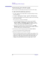
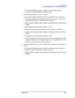
To troubleshoot the 6.0 GHz RF signal path:
1. Set up the analyzer as follows:
a. If it is not already running, start the Vector Signal Analyzer by double
clicking the icon or clicking
Start > (All) Programs > Agilent 89600 VSA
> Vector Signal Analyzer
.
b. Click
File > Preset > Preset Setup.
c. Click
Utilities > Calibration,
and clear the
Apply Corrections to Data
checkbox.
d. Click
MeasSetup > Frequency Bands > 36 MHz
–
6 GHz
.
e. Disconnect the BNC cable from the E1439
Analog In
connector and
connect a signal generator to E1439 Analog Input.
f. Set the signal generator for 70 MHz, –10 dBm output.
g. Set the analyzer’s marker to peak by right clicking on the spectrum trace
and clicking
↑
Peak
. The marker reading should be 20 dBm ± 1.5 dB
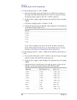
h. Verify the other settings in the following table.
If any of the readings are incorrect, the E1439 module is most likely faulty.
2. Reconnect the BNC cable to the E1439
Analog In
and disconnect the SMA
cable from the 89605
From 70 MHz IF Out
connector. Connect the signal
generator output to 89605
From 70 MHz IF Out
.
a. Set the marker to peak by right clicking on the spectrum trace and clicking
↑
Peak
.
b. The marker reading should be –40 dBm ± 1.5 dB.
If this reading is incorrect, the 89605 module is most likely faulty.
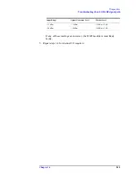
Input Range
Signal Generator Level
Marker Level
+20 dBm
–10 dBm
+20 dBm ± 1.5 dB
–35 dBm
–20 dBm
–40 dBm ± 1.5 dB
–40 dBm
–20 dBm
–40 dBm ± 1.5 dB
–45 dBm
–20 dBm
–40 dBm ± 1.5 dB
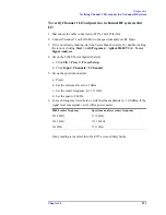
Summary of Contents for 89604
Page 2: ...Agilent Technologies Agilent 89600 Series Installation and VXI Service Guide ...
Page 14: ...13 1 Installation Overview ...
Page 23: ...22 Chapter1 Installation Overview 89600 Series Analyzer Installation and Setup ...
Page 24: ...23 2 Installing 89600 Software ...
Page 32: ...31 3 Setting Up VXI Hardware ...
Page 77: ...76 Chapter3 Setting Up VXI Hardware Connecting EMC grounding cable ...
Page 78: ...77 4 Installing IEEE 1394 Interfaces in Computers ...
Page 86: ...85 5 Installing GPIB LA1 and USB Interface Cards ...
Page 93: ...92 Chapter5 Installing GPIB LAN and USB Interface Cards Configuring a LA1 to GPIB gateway ...
Page 94: ...93 6 Configuring IO Interfaces ...
Page 112: ...111 7 Configuring Infiniium Windows XP Scopes ...
Page 126: ...125 8 Installing 89601 Software in Agilent Infiniium XP Scopes ...
Page 132: ...131 9 Installing Agilent 89600 Software in Agilent X Series Signal Analyzers ...
Page 138: ...137 10 Linking Logic Analyzers to the Agilent 89600 VSA ...
Page 152: ...Chapter 10 151 Linking Logic Analyzers to the Agilent 89600 VSA Logic Analyzer Link Examples ...
Page 156: ...Chapter 10 155 Linking Logic Analyzers to the Agilent 89600 VSA Logic Analyzer Link Examples ...
Page 161: ...160 Chapter10 Linking Logic Analyzers to the Agilent 89600 VSA Logic Analyzer Link Examples ...
Page 162: ...161 11 Linking a Synthetic Instrument SI Spectrum Analyzer to the Agilent 89600 VSA ...
Page 170: ...169 12 Connecting Acqiris Waveform Digitizers to the Agilent 89600 VSA ...
Page 188: ...187 13 Installing a 1ode Locked License ...
Page 198: ...197 14 Setting Up a Floating License Server ...
Page 216: ...215 15 Setting Up a Floating License Client ...
Page 222: ...221 16 Diagnostics ...
Page 254: ...253 17 Circuit Descriptions ...
Page 277: ...276 Chapter18 Replacing VXI Hardware Storing VXI modules ...
Page 281: ...280 Index Index ...
Page 282: ...281 ...


