Chapter 17
257
Circuit Descriptions
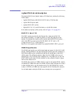
Agilent 89610 circuit description
E1438 ADC Module
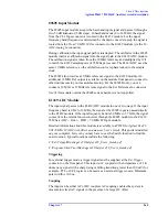
All signal processing happens in the Agilent E1438A 100 MSa/s ADC +
FIFO (attenuation, anti-alias filtering, etc.). Detailed information about this
module is available in a PDF file:
Agilent E1438 VXI 100 MSa/s ADC with filters
and memory User’s Guide
. This guide is installed on your computer, however, you
may have to use the Search function to find the exact location. Typical locations
include the following:
C:/Vxi/Vxipnp/Winnt/age1438/help/e1438_Users_Guide.pdf
C:/Program Files/Visa/Winnt/age1438\help/e1438_Users_Guide.pdf
Triggering
For external trigger mode, a trigger signal must be supplied at the
Ext Trigger
connector on the front panel. This input is AC coupled with an impedance of 1 K
ohm so any signal with a sharp rising or falling transition greater than 100 mV (for
example, TTL or ECL logic) can be used as an external trigger source. Minimum
pulse width is 300 ns.
If your system includes two E1438 modules, you can use the external trigger
connector on either module. The bi-directional Intermodule Sync connectors on
the module front panels connect the trigger signal between the modules. This
synchronizes the two modules so that they receive the trigger signal
simultaneously.
Coupling
The input can be either AC or DC coupled. AC coupling enables the system to
measure low level AC signals in the presence of a large DC offset.
Ranging
Attenuation is the first step in the E1438 module. The module provides 0 to 51 dB
of attenuation in 3 dB steps, resulting in analyzer input ranges between -31 dBm
and 20 dBm in 3 dB steps.
Anti-alias filtering
Since the normal ADC sample rate is 100 MHz, a complete representation of the
input signal can be achieved only for bandwidths up to 50 MHz. Frequency
components above 50 MHz can cause ambiguous results (aliasing).
The anti-alias filter attenuates these high frequency components to reduce aliasing.
The anti-alias filter in the Agilent E1438 is flat to 40 MHz and rejects signals
above 60 MHz by at least 90 dB. Thus the 0-40 MHz frequency range of the
sampled signal is
−
90 dB alias free. The filter’s transition band from 40 MHz to 60
MHz affects flatness and enable some aliasing in the sampled signal frequency
range of 40 MHz to 50 MHz.
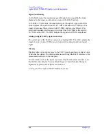
Analog-to-digital (ADC) signal conversion
The central part of the E1438 is a precision sampling ADC. The ADC samples the
Summary of Contents for 89604
Page 2: ...Agilent Technologies Agilent 89600 Series Installation and VXI Service Guide ...
Page 14: ...13 1 Installation Overview ...
Page 23: ...22 Chapter1 Installation Overview 89600 Series Analyzer Installation and Setup ...
Page 24: ...23 2 Installing 89600 Software ...
Page 32: ...31 3 Setting Up VXI Hardware ...
Page 77: ...76 Chapter3 Setting Up VXI Hardware Connecting EMC grounding cable ...
Page 78: ...77 4 Installing IEEE 1394 Interfaces in Computers ...
Page 86: ...85 5 Installing GPIB LA1 and USB Interface Cards ...
Page 93: ...92 Chapter5 Installing GPIB LAN and USB Interface Cards Configuring a LA1 to GPIB gateway ...
Page 94: ...93 6 Configuring IO Interfaces ...
Page 112: ...111 7 Configuring Infiniium Windows XP Scopes ...
Page 126: ...125 8 Installing 89601 Software in Agilent Infiniium XP Scopes ...
Page 132: ...131 9 Installing Agilent 89600 Software in Agilent X Series Signal Analyzers ...
Page 138: ...137 10 Linking Logic Analyzers to the Agilent 89600 VSA ...
Page 152: ...Chapter 10 151 Linking Logic Analyzers to the Agilent 89600 VSA Logic Analyzer Link Examples ...
Page 156: ...Chapter 10 155 Linking Logic Analyzers to the Agilent 89600 VSA Logic Analyzer Link Examples ...
Page 161: ...160 Chapter10 Linking Logic Analyzers to the Agilent 89600 VSA Logic Analyzer Link Examples ...
Page 162: ...161 11 Linking a Synthetic Instrument SI Spectrum Analyzer to the Agilent 89600 VSA ...
Page 170: ...169 12 Connecting Acqiris Waveform Digitizers to the Agilent 89600 VSA ...
Page 188: ...187 13 Installing a 1ode Locked License ...
Page 198: ...197 14 Setting Up a Floating License Server ...
Page 216: ...215 15 Setting Up a Floating License Client ...
Page 222: ...221 16 Diagnostics ...
Page 254: ...253 17 Circuit Descriptions ...
Page 277: ...276 Chapter18 Replacing VXI Hardware Storing VXI modules ...
Page 281: ...280 Index Index ...
Page 282: ...281 ...


