Chapter 16
247
Diagnostics
Troubleshooting the 70 MHz IF signal path
Troubleshooting the 70 MHz IF signal path
The following procedures direct you through inserting a signal at various points in
the analyzer’s signal path to isolate problems to a specific module. Perform the
steps in the order listed. This test requires a signal generator. See
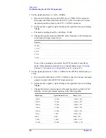
1. Set up the analyzer as follows:
a. If it is not already running, start the Vector Signal Analyzer by double
clicking the icon or clicking
Start > (All) Programs > Agilent 89600 VSA
> Vector Signal Analyzer
.
b. Click
File > Preset > Preset Setup.
c. Click
Utilities > Calibration,
and clear the
Apply Corrections to Data
checkbox.
d. Click
MeasSetup > Frequency Bands > 52 MHz
–
88 MHz
.
e. Click
MeasSetup > Freq > Span,
and enter
100 kHz.
f. Click
Input > Range,
and enter
-45 dBm.
g. Click
Control > Restart
.
h. Disconnect the BNC cable from the E1439
Analog In
connector and
connect a signal generator to E1439 Analog Input.
i. Set the signal generator for 70 MHz, –45 dBm output.
j. Set the 89600 marker to peak: right click on the spectrum trace and click
↑
Peak
. The marker reading should be -39 dBm ± 1.5 dB
k. Click
Markers > Copy Marker to > Move Offset to Mkr
.
l. Change the Input Range in 5 dB increments from -45 dBm to -25 dBm. The
Marker Level for all ranges should read 0 dB ± 0.5 dB.
If any of the readings are incorrect, the E1439 module is most likely faulty.
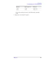
2. Reconnect the BNC cable to the E1439
Analog In
. Connect the signal generator
output to 89605
Ch 1 Input
.
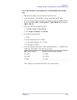
a. Set the marker to peak: right click on the spectrum trace and click
↑
Peak
.
b. Click
Input > Range,
and enter
-25 dBm.
c. Click
Markers > Copy Marker to > Move Offset to Mkr
.
d. Change the Input Range in 5 dB increments from -25 dBm to +20 dBm. The
Marker Level for all ranges should read 0 dB ± 0.5 dB.
If any of these readings is incorrect, the 89605 module is most likely faulty.
3. For a two-channel IF analyzer, repeat this procedure for the second channel.
Summary of Contents for 89604
Page 2: ...Agilent Technologies Agilent 89600 Series Installation and VXI Service Guide ...
Page 14: ...13 1 Installation Overview ...
Page 23: ...22 Chapter1 Installation Overview 89600 Series Analyzer Installation and Setup ...
Page 24: ...23 2 Installing 89600 Software ...
Page 32: ...31 3 Setting Up VXI Hardware ...
Page 77: ...76 Chapter3 Setting Up VXI Hardware Connecting EMC grounding cable ...
Page 78: ...77 4 Installing IEEE 1394 Interfaces in Computers ...
Page 86: ...85 5 Installing GPIB LA1 and USB Interface Cards ...
Page 93: ...92 Chapter5 Installing GPIB LAN and USB Interface Cards Configuring a LA1 to GPIB gateway ...
Page 94: ...93 6 Configuring IO Interfaces ...
Page 112: ...111 7 Configuring Infiniium Windows XP Scopes ...
Page 126: ...125 8 Installing 89601 Software in Agilent Infiniium XP Scopes ...
Page 132: ...131 9 Installing Agilent 89600 Software in Agilent X Series Signal Analyzers ...
Page 138: ...137 10 Linking Logic Analyzers to the Agilent 89600 VSA ...
Page 152: ...Chapter 10 151 Linking Logic Analyzers to the Agilent 89600 VSA Logic Analyzer Link Examples ...
Page 156: ...Chapter 10 155 Linking Logic Analyzers to the Agilent 89600 VSA Logic Analyzer Link Examples ...
Page 161: ...160 Chapter10 Linking Logic Analyzers to the Agilent 89600 VSA Logic Analyzer Link Examples ...
Page 162: ...161 11 Linking a Synthetic Instrument SI Spectrum Analyzer to the Agilent 89600 VSA ...
Page 170: ...169 12 Connecting Acqiris Waveform Digitizers to the Agilent 89600 VSA ...
Page 188: ...187 13 Installing a 1ode Locked License ...
Page 198: ...197 14 Setting Up a Floating License Server ...
Page 216: ...215 15 Setting Up a Floating License Client ...
Page 222: ...221 16 Diagnostics ...
Page 254: ...253 17 Circuit Descriptions ...
Page 277: ...276 Chapter18 Replacing VXI Hardware Storing VXI modules ...
Page 281: ...280 Index Index ...
Page 282: ...281 ...


