Chapter 3
53
Setting Up VXI Hardware
Connecting front panel cables
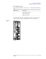
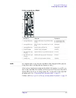
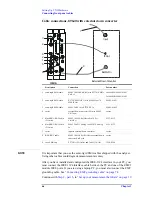
Cable connections, two-channel 89610
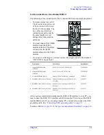
The following cable connections for the 2-channel 89610 are especially important:
• You must connect one set of
Clock connectors and one set
of Sync connectors between
the two E1438 modules. The
two cables used for these
connections must be exactly
the same length to avoid
timing and synchronization
problems.
• You must connect the 10 MHz
Ref Out from the 89606
module to the Ext Clock/Ref
connector on the E1438
module adjacent to the 89606
module.
• If you use external trigger, you must connect the trigger signal to the channel 1
ADC (E1438) trigger input.
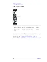
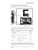
After you have installed and configured the IEEE-1394 interface in your PC, you
must connect the IEEE 1394 interface cable between the PC and one of the E8491
module IEEE ports. If you are using a laptop PC, you must also connect the EMC
grounding cable. See
“Connecting EMC grounding cable” on page 74
Continue with
“Set up your measurement hardware” on page 19
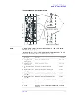
Description
Connection
Part number
1
orange SMB-SMB cable
(100 mm)
E1438 #1
Clock
to E1438 #2
Clock
03585-61603
2
orange SMB-SMB cable
(100 mm)
E1438 #1
Sync
to E1438 #2
Sync
03585-61603
3
50 ohm SMB term (Qty 4)
Unused E1438
Clock
&
Sync
connectors
1250-0676
4
black BNC-BNC cable (172 mm)
89606
10 MHz Ref Out
to E1438A #1
Ext
Clock/Ref
8120-6237
5
black BNC-BNC cable (215 mm)
89606
To ADC 2 Analog In
to E1438A #2
Analog In
8121-0132
6
black BNC-BNC cable (267 mm)
89606
To ADC 1 Analog In
to E1438A #1
Analog In
8121-0133
3
6
5
1
3
2
4
89606B E1438
E1438
Summary of Contents for 89604
Page 2: ...Agilent Technologies Agilent 89600 Series Installation and VXI Service Guide ...
Page 14: ...13 1 Installation Overview ...
Page 23: ...22 Chapter1 Installation Overview 89600 Series Analyzer Installation and Setup ...
Page 24: ...23 2 Installing 89600 Software ...
Page 32: ...31 3 Setting Up VXI Hardware ...
Page 77: ...76 Chapter3 Setting Up VXI Hardware Connecting EMC grounding cable ...
Page 78: ...77 4 Installing IEEE 1394 Interfaces in Computers ...
Page 86: ...85 5 Installing GPIB LA1 and USB Interface Cards ...
Page 93: ...92 Chapter5 Installing GPIB LAN and USB Interface Cards Configuring a LA1 to GPIB gateway ...
Page 94: ...93 6 Configuring IO Interfaces ...
Page 112: ...111 7 Configuring Infiniium Windows XP Scopes ...
Page 126: ...125 8 Installing 89601 Software in Agilent Infiniium XP Scopes ...
Page 132: ...131 9 Installing Agilent 89600 Software in Agilent X Series Signal Analyzers ...
Page 138: ...137 10 Linking Logic Analyzers to the Agilent 89600 VSA ...
Page 152: ...Chapter 10 151 Linking Logic Analyzers to the Agilent 89600 VSA Logic Analyzer Link Examples ...
Page 156: ...Chapter 10 155 Linking Logic Analyzers to the Agilent 89600 VSA Logic Analyzer Link Examples ...
Page 161: ...160 Chapter10 Linking Logic Analyzers to the Agilent 89600 VSA Logic Analyzer Link Examples ...
Page 162: ...161 11 Linking a Synthetic Instrument SI Spectrum Analyzer to the Agilent 89600 VSA ...
Page 170: ...169 12 Connecting Acqiris Waveform Digitizers to the Agilent 89600 VSA ...
Page 188: ...187 13 Installing a 1ode Locked License ...
Page 198: ...197 14 Setting Up a Floating License Server ...
Page 216: ...215 15 Setting Up a Floating License Client ...
Page 222: ...221 16 Diagnostics ...
Page 254: ...253 17 Circuit Descriptions ...
Page 277: ...276 Chapter18 Replacing VXI Hardware Storing VXI modules ...
Page 281: ...280 Index Index ...
Page 282: ...281 ...


