101
Chapter 4 Features and Functions
Digital I/O Operation
4
4
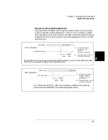
Read and Write Strobe Mode #4
Read and Write Strobe Mode #4 uses the I/O direction line as a Strobe
pulse to indicate writing operations. The PCTL line is used to indicate
Read operations. It is thus similar to the R/W and Strobe Mode #3 except
separate control lines are used for the Strobe pulses and there is no I/O
direction line.
DATA VALID
DATA LINES
W rite O pe ratio n
IO DIRECTION (WR)
t1
40
µ
s
t2
20
µ
s
t 1 = T im e fr om d a t a
v a lid to w r ite
S tr ob e
t 2 = S tro b e p u ls e w id th
(2 0
µ
s m in im u m )
The IO Direction line is used to indicate that the data is valid on the data bus lines.
IO Direction is used to trigger the receiving device.
(4 0
µ
s m in im u m )
DATA LINES
R e a d O p era tio n
PCTL (RD) LINE
t1
100
µ
s
t2
20
µ
s
t1 = T im e from o u tp u t
d is a b le to rea d
S tr ob e (1 0 0
µ
s
t 2 = S tr ob e p u ls e w id th
(2 0
µ
s m in im u m )
DATA VALID
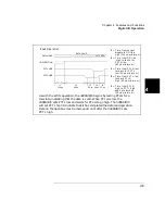
As in Mode #3, the PCTL (RD) line is used to indicate to the sending
device that the 3499A/B/C has latched (read) the data.
m in im u m )
Summary of Contents for Agilent 3499A
Page 13: ...1 1 Quick Start ...
Page 27: ...2 2 Front Panel Operation ...
Page 55: ...3 3 System Overview ...
Page 77: ...4 4 Features and Functions ...
Page 113: ...5 5 Remote Interface Reference ...
Page 164: ...164 5 ...
Page 165: ...6 6 Error Messages ...
Page 173: ...7 7 Plug in Modules ...
Page 256: ...256 Chapter 7 Plug in Modules 44475A Breadboard Module 7 ...
Page 261: ...261 Chapter 7 Plug in Modules 44476B Microwave Switch Module 4 7 The 44476B is shown below ...
Page 286: ...286 Chapter 7 Plug in Modules Terminals and Connections Information 7 ...
Page 288: ...288 7 ...
Page 289: ...8 8 Application Programs ...
Page 299: ...9 9 Specifications ...
Page 343: ...343 Chapter 9 Specifications 44475A Breadboard Module 4 9 ...

