248
Chapter 7 Plug-in Modules
44474A 16-Bit Digital I/O Module
7
44474A 16-Bit Digital I/O Module
The Agilent 44474A Digital I/O module provides 16 bidirectional data
lines (bits) plus 4 lines used for control and handshaking. All lines are
TTL compatible. The 16 I/O lines or bits can be addressed individually
(bit-by-bit), as two independent 8-bit ports, or as one 16-bit word.
The two 8-bit ports are completely independent of each other and may be
used separately. For instance, one port can be used for output operations,
while the other for input. However, all 8 bits in a given port must be
either input or output bits (not a combination of input and output).
Five handshaking modes are available for this module. The handshaking
modes are described beginning on page 98. Handshaking uses up to
three control lines:
•
Peripheral Control (PCTL)
•
I/O direction (I/O)
•
Peripheral Flag (PFLG or EI)
Additionally, the 44474A provides an additional Channel Closed (CC)
line that changes state to indicate a channel has been closed. The
External Increment (EI) and Channel Closed (CC) lines can be used to
control an external instrument such as a DMM. For example, Agilent
DMMs have a Voltmeter Complete line that indicates when a
measurement has completed. This line is connected to the 44474A EI
input and the Channel Closed output is connected to the DMM External
Trigger. When properly configured, a scan list can then be executed and
measured without external computer control.
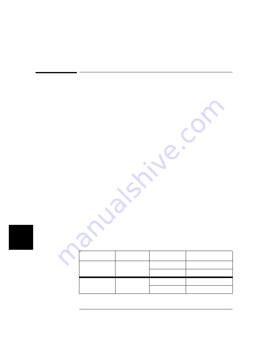
Port and bit numbering is show in the table below. Note that the ports
are numbered differently if you are using the 3488 System mode.
Specifications for the 44474A are given on page 341.
System Mode
16-Bit Port #
8-Bit Port #
Bit #
SCPI mode
PORT 00
PORT 00
Bits 0-7 (LO BYTE)
PORT 01
Bits 0-7 (HI BYTE)
3488A Mode
PORT 02
PORT 00
Bits 0-7 (LO BYTE)
PORT 01
Bits 0-7 (HI BYTE)
Summary of Contents for Agilent 3499A
Page 13: ...1 1 Quick Start ...
Page 27: ...2 2 Front Panel Operation ...
Page 55: ...3 3 System Overview ...
Page 77: ...4 4 Features and Functions ...
Page 113: ...5 5 Remote Interface Reference ...
Page 164: ...164 5 ...
Page 165: ...6 6 Error Messages ...
Page 173: ...7 7 Plug in Modules ...
Page 256: ...256 Chapter 7 Plug in Modules 44475A Breadboard Module 7 ...
Page 261: ...261 Chapter 7 Plug in Modules 44476B Microwave Switch Module 4 7 The 44476B is shown below ...
Page 286: ...286 Chapter 7 Plug in Modules Terminals and Connections Information 7 ...
Page 288: ...288 7 ...
Page 289: ...8 8 Application Programs ...
Page 299: ...9 9 Specifications ...
Page 343: ...343 Chapter 9 Specifications 44475A Breadboard Module 4 9 ...

