264
Chapter 7 Plug-in Modules
44476B Microwave Switch Module
7
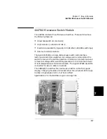
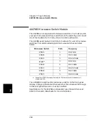
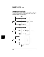
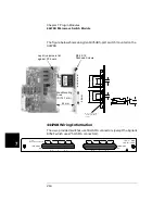
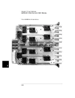
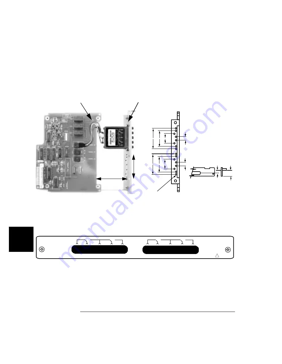
The figure below shows an Agilent 8764B 5-port switch mounted on the
44476B.
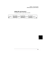
44476B Wiring Information
The user-provided switches use 50
Ω
SMA connectors (except the Agilent
8762F which uses 75
Ω
SMA connectors).
All mounting holes
threaded for M2.5
screws
55.58 44.44 30.1
11.2
55.58 44.44 30.1
11.2
7.01
16.42
M2.5 X 18
Panhead Screws
Lay drive jumpers flat
against PC board
Max Mounting
Area
(D=14.1 mm)
62 mm
66 m
m
44476B
MICROWAVE SWITCH
CHANNEL
00
1
2
3
4
5
1
2
3
4
5
NO
C
NC
NO
C
NC
CHANNEL
01
7VDC = MAX
1WCW / CHAN
!
Summary of Contents for Agilent 3499A
Page 13: ...1 1 Quick Start ...
Page 27: ...2 2 Front Panel Operation ...
Page 55: ...3 3 System Overview ...
Page 77: ...4 4 Features and Functions ...
Page 113: ...5 5 Remote Interface Reference ...
Page 164: ...164 5 ...
Page 165: ...6 6 Error Messages ...
Page 173: ...7 7 Plug in Modules ...
Page 256: ...256 Chapter 7 Plug in Modules 44475A Breadboard Module 7 ...
Page 261: ...261 Chapter 7 Plug in Modules 44476B Microwave Switch Module 4 7 The 44476B is shown below ...
Page 286: ...286 Chapter 7 Plug in Modules Terminals and Connections Information 7 ...
Page 288: ...288 7 ...
Page 289: ...8 8 Application Programs ...
Page 299: ...9 9 Specifications ...
Page 343: ...343 Chapter 9 Specifications 44475A Breadboard Module 4 9 ...


