43
Chapter 2 Front-Panel Operation
To Configure for External Trigger
4
2
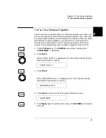
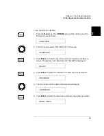
4. Turn the knob to select the slot for the external trigger. Slot 0 (control
module) is the built-in external trigger (available at the rear panel
mini DIN connector, see page 7). If a 44474A is not installed, only slot
0 will be shown. Press Enter. The display shows the current setting
for the external trigger.
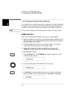
5. Turn the knob to show the alternate choice.
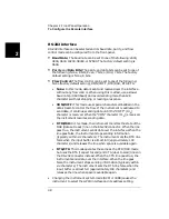
6. Press Enter to accept the choice and return to the first level menu.
7. Press the Menu key to exit the menu. The CONFIG annunciator
turns off.
DISABLE
ENABLE
CONF EXT TRIG
Summary of Contents for Agilent 3499A
Page 13: ...1 1 Quick Start ...
Page 27: ...2 2 Front Panel Operation ...
Page 55: ...3 3 System Overview ...
Page 77: ...4 4 Features and Functions ...
Page 113: ...5 5 Remote Interface Reference ...
Page 164: ...164 5 ...
Page 165: ...6 6 Error Messages ...
Page 173: ...7 7 Plug in Modules ...
Page 256: ...256 Chapter 7 Plug in Modules 44475A Breadboard Module 7 ...
Page 261: ...261 Chapter 7 Plug in Modules 44476B Microwave Switch Module 4 7 The 44476B is shown below ...
Page 286: ...286 Chapter 7 Plug in Modules Terminals and Connections Information 7 ...
Page 288: ...288 7 ...
Page 289: ...8 8 Application Programs ...
Page 299: ...9 9 Specifications ...
Page 343: ...343 Chapter 9 Specifications 44475A Breadboard Module 4 9 ...


