6
The Rear Panel at a Glance
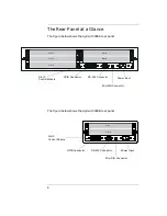
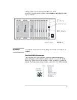
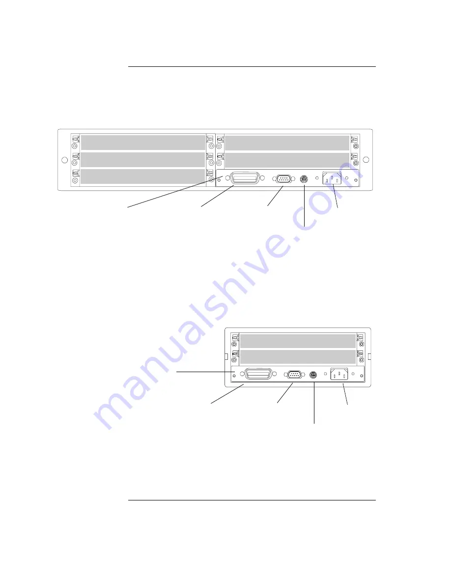
The figure below shows the Agilent 3499A rear panel.
The figure below shows the Agilent 3499B rear panel.
Slot 4
Slot 5
Slot 1
Slot 2
Slot 3
GPIB Connector
RS-232 Connector
Mini DIN Connector
Power Input
Slot 0
Control Module
Slot 1
Slot 2
GPIB Connector
RS-232 Connector
Mini DIN Connector
Power Input
Slot 0
Control Module
Summary of Contents for Agilent 3499A
Page 13: ...1 1 Quick Start ...
Page 27: ...2 2 Front Panel Operation ...
Page 55: ...3 3 System Overview ...
Page 77: ...4 4 Features and Functions ...
Page 113: ...5 5 Remote Interface Reference ...
Page 164: ...164 5 ...
Page 165: ...6 6 Error Messages ...
Page 173: ...7 7 Plug in Modules ...
Page 256: ...256 Chapter 7 Plug in Modules 44475A Breadboard Module 7 ...
Page 261: ...261 Chapter 7 Plug in Modules 44476B Microwave Switch Module 4 7 The 44476B is shown below ...
Page 286: ...286 Chapter 7 Plug in Modules Terminals and Connections Information 7 ...
Page 288: ...288 7 ...
Page 289: ...8 8 Application Programs ...
Page 299: ...9 9 Specifications ...
Page 343: ...343 Chapter 9 Specifications 44475A Breadboard Module 4 9 ...

