97
Chapter 4 Features and Functions
Digital I/O Operation
4
4
•
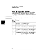
Remote Interface Operation: Set the flow control parameters using the
following SCPI commands. These examples assume a digital I/O
module is installed in slot 4.
SOURce:DIGital:MODE 4,1
! Set the flow control mode to
Mode 1.
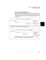
SOURce:DIGital:CONTrol:POLarity 4,1
! Set the PCTL line polarity to
negative.
SOURce:DIGital:FLAG:POLarity 4,0
! Set the PFLG line polarity to
positive.
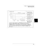
SOURce:DIGital:IO:POLarity 4,1
! Set the I/O Direction line
polarity to negative.
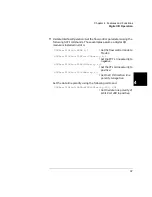
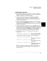
Set the data line polarity using the following command.
SOURce:DIGital:DATA:BYTE:POLarity 400, POS
! Set the data line polarity of
8-bit Port 400 to positive.
Summary of Contents for Agilent 3499A
Page 13: ...1 1 Quick Start ...
Page 27: ...2 2 Front Panel Operation ...
Page 55: ...3 3 System Overview ...
Page 77: ...4 4 Features and Functions ...
Page 113: ...5 5 Remote Interface Reference ...
Page 164: ...164 5 ...
Page 165: ...6 6 Error Messages ...
Page 173: ...7 7 Plug in Modules ...
Page 256: ...256 Chapter 7 Plug in Modules 44475A Breadboard Module 7 ...
Page 261: ...261 Chapter 7 Plug in Modules 44476B Microwave Switch Module 4 7 The 44476B is shown below ...
Page 286: ...286 Chapter 7 Plug in Modules Terminals and Connections Information 7 ...
Page 288: ...288 7 ...
Page 289: ...8 8 Application Programs ...
Page 299: ...9 9 Specifications ...
Page 343: ...343 Chapter 9 Specifications 44475A Breadboard Module 4 9 ...


