99
Chapter 4 Features and Functions
Digital I/O Operation
4
4
Static Mode #1
Static Mode #1 is the default mode. In this mode, data is transferred
statically, there is no read or write strobe pulses or handshaking. The I/O
Direction line is active and indicates direction of transfer. This is shown
in the following timing diagrams.
Static Mode #2
Static Mode #2 acts just like Mode #1 except the output lines are not
disabled during an input operation. This means that if a port is written
to and then read from, the data read will be that which was just written
to it. It is possible, however, that external devices might load the lines
and cause a false read.
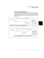
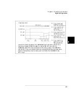
Timing for the I/O direction line is as shown in Mode #1 for write
operations. For read operations, the I/O direction line does not change.
DATA VALID
DATA LINES
I/O DIRECTION
t1 = I/O in p u t to d at a
v a li d (1 m s m i n im u m )
t1 (>1ms)
Write Operation
(CLOSE, DWRITE, etc.)
Approximately 1 ms after the I/O direction line goes to
a low
s
tate, the digital I/O module takes control of the data lines.
DATA VALID
DATA LINES
I/O DIRECTION
t1 = D a ta b u s fl oa te d
Read Operation
(DREAD, etc.)
t1
t2
100
µ
s
150
µ
s
to I /O in p u t
(
1 0 0
µ
s m i n im u m )
t2 = I/O in p u t to d a ta
l a tc h e d (1 5 0
µ
s
m in im u m )
100
µ
s after the 3499A/B/C is instructed to read the data lines, it releases
control of the lines and the I/O direction line goes to a high state. 150
µ
s
later the data is actually read (latched).
Summary of Contents for Agilent 3499A
Page 13: ...1 1 Quick Start ...
Page 27: ...2 2 Front Panel Operation ...
Page 55: ...3 3 System Overview ...
Page 77: ...4 4 Features and Functions ...
Page 113: ...5 5 Remote Interface Reference ...
Page 164: ...164 5 ...
Page 165: ...6 6 Error Messages ...
Page 173: ...7 7 Plug in Modules ...
Page 256: ...256 Chapter 7 Plug in Modules 44475A Breadboard Module 7 ...
Page 261: ...261 Chapter 7 Plug in Modules 44476B Microwave Switch Module 4 7 The 44476B is shown below ...
Page 286: ...286 Chapter 7 Plug in Modules Terminals and Connections Information 7 ...
Page 288: ...288 7 ...
Page 289: ...8 8 Application Programs ...
Page 299: ...9 9 Specifications ...
Page 343: ...343 Chapter 9 Specifications 44475A Breadboard Module 4 9 ...


