129
Chapter 5 Remote Interface Reference
Specific Plug-in Module Commands
4
5
Specific Plug-in Module Commands
[ROUTe:]
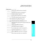
CPAir <slot1>,<slot2>|-1
CPAir?
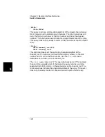
This command is used to group two cards of the same type together -
effectively assigning both cards to both slot numbers. When a command
is sent to one of the paired cards, that command is executed on both
cards in succession - lowest slot number first. The card pair feature is
especially useful when doing 4-wire scanning. Only two identical plug-in
modules can be paired. Modules that can be paired include the switching
modules (MUX, GP and Matrix), the digital I/O modules, and the
multifunction modules.
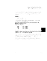
The slot 0 refers to the 3499A/B/C control board. Valid slot numbers are:
After two switching modules are paired, opening/closing/scanning one or
more channels on either one of the paired modules will result in the same
operation on the respective channels on the other module being
performed at the same time.
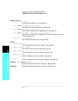
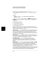
The N2260A and N2266A are configurable MUX modules. Only when
both modules are configured to the same function, can the two modules
be paired. Once paired, changing the function of one module will be
duplicated on the other module in the pair. Page 130 gives additional
details about the N2260A and N2266A configuration.
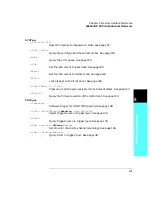
You can pair DIO modules if they are used in handshake Mode #1 or #2
(but not in Mode #3 or #4 or #5). Once paired, writing data on either one
of the paired modules will write the data on the other module.
You can cancel a card pair by specifying a “-1” for the second <slot>
parameter. There will be no paired cards after an instrument power-on
or reset.
The
ROUTe:CPAir?
query returns a list of four numbers separated with
commas, indicating the four slots in which two pairs of modules are
plugged. If there is only one pair, “0,0” will be returned for the last two
numbers.
0,0,0,0 is returned if no cards are paired.
3499A
slots 1 through 5
3499B
slots 1 through 2
3499C
slots 1 through 9
Summary of Contents for Agilent 3499A
Page 13: ...1 1 Quick Start ...
Page 27: ...2 2 Front Panel Operation ...
Page 55: ...3 3 System Overview ...
Page 77: ...4 4 Features and Functions ...
Page 113: ...5 5 Remote Interface Reference ...
Page 164: ...164 5 ...
Page 165: ...6 6 Error Messages ...
Page 173: ...7 7 Plug in Modules ...
Page 256: ...256 Chapter 7 Plug in Modules 44475A Breadboard Module 7 ...
Page 261: ...261 Chapter 7 Plug in Modules 44476B Microwave Switch Module 4 7 The 44476B is shown below ...
Page 286: ...286 Chapter 7 Plug in Modules Terminals and Connections Information 7 ...
Page 288: ...288 7 ...
Page 289: ...8 8 Application Programs ...
Page 299: ...9 9 Specifications ...
Page 343: ...343 Chapter 9 Specifications 44475A Breadboard Module 4 9 ...

