134
Chapter 5 Remote Interface Reference
Scanning Commands
5
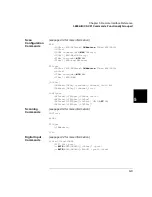
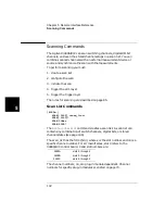
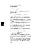
Scan Configuration Commands
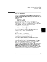
These command set the arm and trigger layer parameters. See “The Scan
Process” on page 86 for a complete description of the layers and scan
configuration process.
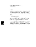
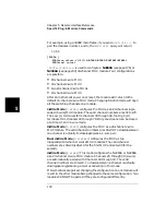
ARM
:SOURce <BUS|EXTernal|IMMediate|TIMer|MIX|HOLD>
:SOURce?
This command specifies the event control source for the arm layer. A
complete description of the arm layer and how it relates to scanning
begins on page 85. The ARM source can be specified to be one of the
following:
•
BUS
-
the sweep of the scan list starts after a
*TRG
or
GET
is received.
•
EXTernal
- the sweep of scan list starts after an external trigger is
received.
•
IMMediate
- the sweep of scan starts immediately after
INITiate
(
or the end of a scan if multiple scans are specified).
•
TIMer
- the sweep of the scan list starts after the timer interval.
•
MIX
- the scan will continue after a
BUS
or
EXTernal
event occurs.
•
HOLD
- the sweep of the scan list starts when a
TRIGger[:IMMediate]
command is received.
After the power is applied or a reset (
*RST
) command is received, the
default ARM source is
IMMediate
.
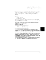
The
ARM:SOURce?
query returns a string. Possible values retuned
include:
BUS
,
EXTernal
,
IMMediate
,
TIMer
,
MIX
, or
HOLD
.
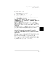
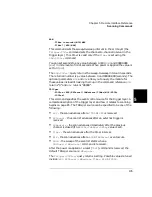
ARM
:COUNt <number>|MIN|MAX|INFinity
:COUNt? [MIN|MAX|INFinity]
This command sets the number of times the scan list is performed.
MIN
specifies a single sweep,
MAX
specifies 99,999 sweeps, and
INF
continues
sweeping the scan list indefinitely (until an
ABORt
command is received).
Following power on or a reset (
*RST
) command, the
ARM:COUNt
is set to
1 (
MIN
).
The
ARM:COUNt?
query returns the number of scanning cycles set by
ARM:COUNt
. The optional parameters
MIN
and
MAX
allow you to query
the module for these values instead of looking them up in the command
reference.
MIN
returns “1”,
MAX
returns “99999”, and
INF
returns “-1”.
Summary of Contents for Agilent 3499A
Page 13: ...1 1 Quick Start ...
Page 27: ...2 2 Front Panel Operation ...
Page 55: ...3 3 System Overview ...
Page 77: ...4 4 Features and Functions ...
Page 113: ...5 5 Remote Interface Reference ...
Page 164: ...164 5 ...
Page 165: ...6 6 Error Messages ...
Page 173: ...7 7 Plug in Modules ...
Page 256: ...256 Chapter 7 Plug in Modules 44475A Breadboard Module 7 ...
Page 261: ...261 Chapter 7 Plug in Modules 44476B Microwave Switch Module 4 7 The 44476B is shown below ...
Page 286: ...286 Chapter 7 Plug in Modules Terminals and Connections Information 7 ...
Page 288: ...288 7 ...
Page 289: ...8 8 Application Programs ...
Page 299: ...9 9 Specifications ...
Page 343: ...343 Chapter 9 Specifications 44475A Breadboard Module 4 9 ...

