140
Chapter 5 Remote Interface Reference
Digital I/O Commands
5
Digital Configuration Commands
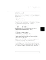
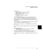
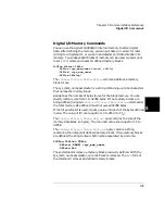
These commands set the digital I/O handshake mode, handshake line
polarities, and data line polarities. The port parameter is in the form
snn, where s is the slot number and nn is the first channel on the digital
port. The port parameter is plug-in module dependent. Valid port
numbers for each plug-in module are shown beginning on page 70.
SOURce:DIGital
:MODE <port>,<mode>
:MODE? <port>
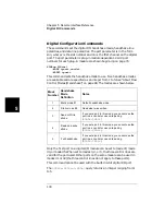
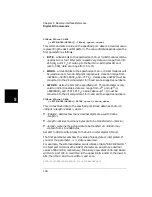
This command sets the handshake mode to use. Five handshake modes
are available and are specified as an integer from 1 to 5. See “About Flow
Control Modes (Handshake)” on page 98. The modes are shown below.
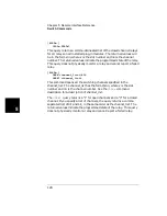
Only the first port on a digital I/O module can be set to mode #3, mode
#4, or mode #5. When set to modes 3, 4, or 5, the three control lines are
valid for the port used. Other ports on the same module can be used in
modes #1 or #2 (the three control lines do not apply to these ports).
This command cannot be used with the built-in 4-bit digital I/O port.
The
SOURce:DIGital:MODe?
query returns an integer ranging from 1
to 5.
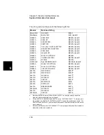
Mode
Number
Handshake
Mode
Definition
Notes
1
Static mode #1
Default handshake mode.
2
Static mode #2
Read what was written.
3
Read or Write
strobe
If you set a port to this mode, you cannot use the
port in a scan list or use card pairing
(
ROUTe:CPAir
).
4
Read and write
strobe
If you set a port to this mode, you cannot use the
port in a scan list or use card pairing
(
ROUTe:CPAir
).
5
Full
handshake
If you set a port to this mode, you cannot use the
port in a scan list or use card pairing
(
ROUTe:CPAir
).
Summary of Contents for Agilent 3499A
Page 13: ...1 1 Quick Start ...
Page 27: ...2 2 Front Panel Operation ...
Page 55: ...3 3 System Overview ...
Page 77: ...4 4 Features and Functions ...
Page 113: ...5 5 Remote Interface Reference ...
Page 164: ...164 5 ...
Page 165: ...6 6 Error Messages ...
Page 173: ...7 7 Plug in Modules ...
Page 256: ...256 Chapter 7 Plug in Modules 44475A Breadboard Module 7 ...
Page 261: ...261 Chapter 7 Plug in Modules 44476B Microwave Switch Module 4 7 The 44476B is shown below ...
Page 286: ...286 Chapter 7 Plug in Modules Terminals and Connections Information 7 ...
Page 288: ...288 7 ...
Page 289: ...8 8 Application Programs ...
Page 299: ...9 9 Specifications ...
Page 343: ...343 Chapter 9 Specifications 44475A Breadboard Module 4 9 ...


