141
Chapter 5 Remote Interface Reference
Digital I/O Commands
4
5
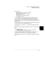
SOURce:DIGital
:CONTrol:POLarity <slot>,<0|1|POS|NEG>
:CONTrol:POLarity? <slot>
:FLAG:POLarity <slot>,<0|1|POS|NEG>
:FLAG:POLarity? <slot>
:IO:POLarity <slot>,<0|1|POS|NEG>
:IO:POLarity? <slot>
These commands set the polarity of the three handshake lines. The
CONTrol
portion of the command works with the PCTL (Peripheral
control) line. The
FLAG
portion of the command works with the PFLG
(peripheral flag) line. The
IO
portion of the command works with the I/O
direction line.
The slot parameter is a decimal ranging from 1 to 5. These commands do
not work with the built-in 4-bit digital I/O port (0).
Following power on or a reset (
*RST
) command, the polarities are set to
0
or
POSitive
.
The query versions of these commands return one of two strings: POS or
NEG.
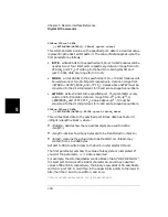
SOURce:DIGital:DATA
[:<BYTE|WORD|LWORD>]:POLarity <port>,<0|1|POS|NEG>
[:<BYTE|WORD|LWORD>]:POLarity? <port>
This command sets the data line polarity for the specified port. The
current state of the data lines is not changed by this command.
Following power on or a reset (
*RST
) command, the polarity is set to 0 or
POS.
Summary of Contents for Agilent 3499A
Page 13: ...1 1 Quick Start ...
Page 27: ...2 2 Front Panel Operation ...
Page 55: ...3 3 System Overview ...
Page 77: ...4 4 Features and Functions ...
Page 113: ...5 5 Remote Interface Reference ...
Page 164: ...164 5 ...
Page 165: ...6 6 Error Messages ...
Page 173: ...7 7 Plug in Modules ...
Page 256: ...256 Chapter 7 Plug in Modules 44475A Breadboard Module 7 ...
Page 261: ...261 Chapter 7 Plug in Modules 44476B Microwave Switch Module 4 7 The 44476B is shown below ...
Page 286: ...286 Chapter 7 Plug in Modules Terminals and Connections Information 7 ...
Page 288: ...288 7 ...
Page 289: ...8 8 Application Programs ...
Page 299: ...9 9 Specifications ...
Page 343: ...343 Chapter 9 Specifications 44475A Breadboard Module 4 9 ...

