144
Chapter 5 Remote Interface Reference
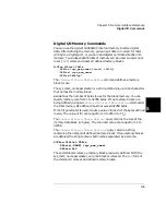
Digital I/O Commands
5
SOURce:DIGital:DATA
[:<BYTE|WORD|LWORD>][:VALue] <port>,<data>
This command sets a value on the specified port. data is a decimal value
representing the desired bit pattern. The value of data depends upon the
first parameter as follows:
•
BYTE -
writes 8 bits to the specified port. 16- or 32-bit modules will be
used as two or four 8-bit ports respectively. data can range from 0 to
255 (00
h
and FF
h
). If writing to the built-in 4-bit digital I/O port
(port = 090), data can range from 0 to 15.
•
WORD -
writes 16 bits to the specified port. 16- or 32-bit modules will
be used as one or two 16-bit ports respectively. data can range from
-32768 to +32767 (-8000
h
and +7FFF
h
). Values above 32767 must be
converted to the 2’s complement form and sent as negative numbers.
•
LWORD
- writes 32 bits to the specified port. This parameter is only
valid on 32-bit modules. data can range from -2
31
and +(2
31
-1)
(-80000000
h
and 7FFFFFFF
h
). Values above +(2
31
-1) must be
converted to the 2’s complement form and sent as negative numbers.
SOURce:DIGital:DATA
[:<BYTE|WORD|LWORD>]:BLOCK <port>,<block_data>
This writes block data to the specified port. Block data has the form:
<#digits><length><block>, where:
•
<#digits> decides how many decimal digits are used to define
<length>;
•
<length> decides how many bytes are to be transferred in <block>;
•
<block> contains the actual data to be transferred. <block> may
contain from 1 to 2048 bytes.
Set port to 090 to write blocks to the built-in 4-bit digital I/O port.
The first parameter sets how the value of block_data is interpreted. If
you omit the parameter,
BYTE
data is assumed.
For example, the command below sends a block of data, “ABCDEFGHIJ”,
to 16-bit port 100. Since the ASCII characters A and B have decimal
values of 65 and 66, respectively, the binary equivalent of 65 and 66 are
written to port 100. A is written to the upper 8 bits and B to the lower 8
bits; then the C and D are written, and so on.
SOUR:DIG:DATA:WORD:BLOCK 100,#210ABCDEFGHIJ
Summary of Contents for Agilent 3499A
Page 13: ...1 1 Quick Start ...
Page 27: ...2 2 Front Panel Operation ...
Page 55: ...3 3 System Overview ...
Page 77: ...4 4 Features and Functions ...
Page 113: ...5 5 Remote Interface Reference ...
Page 164: ...164 5 ...
Page 165: ...6 6 Error Messages ...
Page 173: ...7 7 Plug in Modules ...
Page 256: ...256 Chapter 7 Plug in Modules 44475A Breadboard Module 7 ...
Page 261: ...261 Chapter 7 Plug in Modules 44476B Microwave Switch Module 4 7 The 44476B is shown below ...
Page 286: ...286 Chapter 7 Plug in Modules Terminals and Connections Information 7 ...
Page 288: ...288 7 ...
Page 289: ...8 8 Application Programs ...
Page 299: ...9 9 Specifications ...
Page 343: ...343 Chapter 9 Specifications 44475A Breadboard Module 4 9 ...

