281
Chapter 7 Plug-in Modules
Terminals and Connections Information
4
7
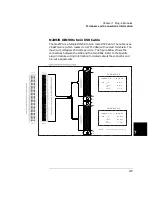
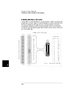
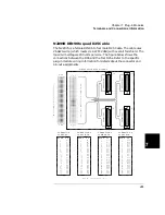
N2299A DIN96 to quad D25 Cable
The N2297A is a female DIN96 to four male D25 Cable. The cable uses
26 AWG wire (which meets UL AWM: 2464) with overall foil shield. The
maximum voltage is 200 volts per wire. The figure below shows the
connections between the D96 and the four D25s. Refer to the specific
plug-in module wiring information for details about the connector and
pin-out assignments.
32
31
30
29
28
27
26
25
24
23
22
21
20
19
18
17
16
15
14
13
12
11
10
9
8
7
6
5
4
3
2
1
96-p
in
femal
e
DI
N
co
nn
ec
tor
(on
the
DI
N-t
o-D
cabl
e)
96
-p
in
mal
e
DI
N
conn
ect
or
(on
the
plu
g-in
mo
du
le)
1
14
13
25
CONNE
CTOR
1
1
14
13
25
CONNE
CTOR
3
13
1
14
25
CONNE
CTOR
2
1
14
13
25
CONNE
CTOR
4
N2299A DIN96-TO-QUAD-D25 CABLE
C
B A
32
31
30
29
28
27
26
25
24
23
22
21
20
19
18
17
16
15
14
13
12
11
10987
6
543
21
C
B A
CONNECTOR 1
vs. 96-PIN DI
N
SUB-D
DIN
1
2
3
4
5
6
7
8
9
10
11
12
13
14
15
16
17
18
19
20
21
22
23
24
25
A1
B1
C1
A3
B3
C3
A5
B5
C5
A7
B7
C7
--
A2
B2
C2
A4
B4
C4
A6
B6
C6
A8
B8
C8
Note: A “--” indicates the p in is not u
SUB-D
DIN
1
2
3
4
5
6
7
8
9
10
11
12
13
14
15
16
17
18
19
20
21
22
23
24
25
A9
B9
C9
A11
B11
C11
A13
B13
C13
A15
B15
C15
--
A10
B10
C10
A12
B12
C12
A14
B14
C14
A16
B16
C16
SUB-D
DIN
1
2
3
4
5
6
7
8
9
10
11
12
13
14
15
16
17
18
19
20
21
22
23
24
25
A17
B17
C17
A19
B19
C19
A21
B21
C21
A23
B23
C23
--
A18
B18
C18
A20
B20
C20
A22
B22
C22
A24
B24
C24
SUB-D
DIN
1
2
3
4
5
6
7
8
9
10
11
12
13
14
15
16
17
18
19
20
21
22
23
24
25
A25
B25
C25
A27
B27
C27
A29
B29
C29
A31
B31
C31
--
A26
B26
C26
A28
B28
C28
A30
B30
C30
A32
B32
C32
CONNECTOR 4
vs. 96-PIN DIN
CONNECTOR 3
vs. 96-PIN DIN
CONNECTOR 2
vs. 96-PIN DIN
Summary of Contents for Agilent 3499A
Page 13: ...1 1 Quick Start ...
Page 27: ...2 2 Front Panel Operation ...
Page 55: ...3 3 System Overview ...
Page 77: ...4 4 Features and Functions ...
Page 113: ...5 5 Remote Interface Reference ...
Page 164: ...164 5 ...
Page 165: ...6 6 Error Messages ...
Page 173: ...7 7 Plug in Modules ...
Page 256: ...256 Chapter 7 Plug in Modules 44475A Breadboard Module 7 ...
Page 261: ...261 Chapter 7 Plug in Modules 44476B Microwave Switch Module 4 7 The 44476B is shown below ...
Page 286: ...286 Chapter 7 Plug in Modules Terminals and Connections Information 7 ...
Page 288: ...288 7 ...
Page 289: ...8 8 Application Programs ...
Page 299: ...9 9 Specifications ...
Page 343: ...343 Chapter 9 Specifications 44475A Breadboard Module 4 9 ...


